NAVIGATION / MULTI INFO DISPLAY TOYOTA MULTI OPERATION TOUCH SYSTEM B1523 DCU GVIF Disconnected (from D-SEAT SW to Multi Display)
DESCRIPTION
The integration control sub-assembly and multi-display assembly are connected via video signal (digital) lines.
This DTC is stored when a video signal (digital) line is disconnected.
| DTC No. | Detection Item | DTC Detection Condition | Trouble Area | DTC Output from | Priority |
|---|---|---|---|---|---|
| B1523 | DCU GVIF Disconnected (from D-SEAT SW to Multi Display) | GVIF disconnected (from integration control sub-assembly to multi-display assembly) |
·
Harness or connector (GVIF cable)
·
Multi-display assembly
·
Integration control sub-assembly |
D-SEAT SW | A |
WIRING DIAGRAM
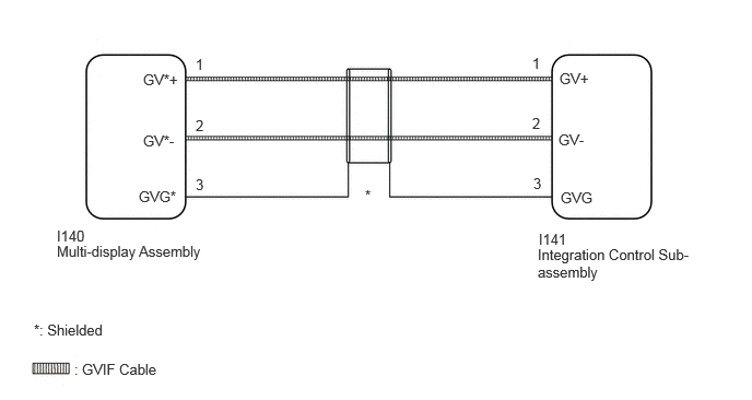
CAUTION / NOTICE / HINT
- NOTICE:
-
When replacing the integration control sub-assembly, always replace it with a new one. If an integration control sub-assembly which was installed to another vehicle is used, the following may occur:
-
·
A communication malfunction DTC may be stored.
·The integration control sub-assembly may not operate normally.
PROCEDURE
Pre-procedure1
Clear the DTCs.
- Body Electrical > D-SEAT SW > Clear DTCs
- 50002 181
Procedure1
Recheck for DTCs and check that no DTCs are output.
- Body Electrical > D-SEAT SW > Trouble Codes
- 50001 181
- Result:
-
Result Proceed to DTCs are not output A DTCs are output B
Post-procedure1
None
A
Click hereGeneral>INTRODUCTION>HOW TO TROUBLESHOOT ECU CONTROLLED SYSTEMS>HOW TO PROCEED WITH TROUBLESHOOTING
B
Pre-procedure1
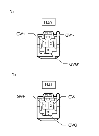
| *a | Front view of wire harness connector (to Multi-display Assembly) |
| *b | Front view of wire harness connector (to Integration Control Sub-assembly) |
Disconnect the I140 multi-display assembly connector.
Disconnect the I141 integration control sub-assembly connector.
Procedure1
Measure the resistance according to the value(s) in the table below.
- Standard Resistance:
-
Tester Connection Condition Specified Condition Click Location & Routing(I140,I141)Location & Routingewd_type=routing;type=c,c;code=I140,I141
I140-1 (GV*+) - I141-1 (GV+) Always Below 1 Ω I140-2 (GV*-) - I141-2 (GV-) Always Below 1 Ω I140-3 (GVG*) - I141-3 (GVG) Always Below 1 Ω I140-1 (GV*+) or I141-1 (GV+) - Body ground Always 10 kΩ or higher I140-2 (GV*-) or I141-2 (GV-) - Body ground Always 10 kΩ or higher I140-3 (GVG*) or I141-3 (GVG) - Body ground Always 10 kΩ or higher
- Result:
-
Proceed to OK NG
Post-procedure1
None
OK
NG
Pre-procedure1
Replace the integration control sub-assembly with a new one.
- HINT:
-
Click hereAudio / Visual / Telematics>NAVIGATION / MULTI INFO DISPLAY>MULTI-DISPLAY ECU>REMOVAL
Clear the DTCs.
- Body Electrical > D-SEAT SW > Clear DTCs
- 50002 181
Procedure1
Recheck for DTCs and check that no DTCs are output.
- Body Electrical > D-SEAT SW > Trouble Codes
- 50001 181
- Result:
-
Result Proceed to DTCs are not output A DTCs are output B
Post-procedure1
None
A
B