RM38G0E _56 Audio / Visual / Telematics _100607 NAVIGATION / MULTI INFO DISPLAY _0467505 TOYOTA MULTI OPERATION TOUCH SYSTEM J
NAVIGATION / MULTI INFO DISPLAY TOYOTA MULTI OPERATION TOUCH SYSTEM Power Source Circuit
DESCRIPTION
This is the power source circuit to operate the integration control sub-assembly.
WIRING DIAGRAM
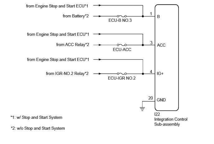
2.104,0.448 3.219,0.656 1.115,0.208 10 false from Battery*2 1.542,2.375 3.313,2.594 1.771,0.219 10 false from IGR-NO.2 Relay*2 3.615,2.531 4.792,2.781 1.177,0.25 10 false ECU-IGR NO.2 3.781,1.573 4.563,1.823 0.781,0.25 10 false ECU-ACC 5.167,3.74 5.479,3.938 0.313,0.198 10 false I22 5.021,0.375 5.177,0.573 0.156,0.198 10 false 1 5.031,1.344 5.344,1.542 0.313,0.198 10 false 3 5.021,2.313 5.333,2.51 0.313,0.198 10 false 4 4.969,3.198 5.219,3.427 0.25,0.229 10 false 20 5.26,0.469 5.427,0.635 0.167,0.167 10 false B 5.26,1.427 5.646,1.615 0.385,0.188 10 false ACC 5.25,2.375 5.563,2.573 0.313,0.198 10 false IG+ 5.25,3.26 5.635,3.438 0.385,0.177 10 false GND 5.167,3.906 6.344,4.469 1.177,0.563 10 false Integration Control Sub-assembly 1.885,1.406 3.208,1.667 1.323,0.26 10 false from ACC Relay*2 3.635,0.594 4.792,0.75 1.156,0.156 10 false ECU-B NO.3 0.875,0.115 3.167,0.396 2.292,0.281 10 false from Engine Stop and Start ECU*1 0.906,1.063 3.198,1.344 2.292,0.281 10 false from Engine Stop and Start ECU*1 0.906,1.906 3.198,2.188 2.292,0.281 10 false from Engine Stop and Start ECU*1 0.354,3.844 3.177,4.115 2.823,0.271 10 false *1: w/ Stop and Start System 0.365,4.208 3.188,4.479 2.823,0.271 10 false *2: w/o Stop and Start System
CAUTION / NOTICE / HINT
- NOTICE:
-
Inspect the fuses for circuits related to this system before performing the following procedure.
PROCEDURE
1.CHECK HARNESS AND CONNECTOR (INTEGRATION CONTROL SUB-ASSEMBLY POWER SOURCE)
a.
Disconnect the I22 integration control sub-assembly connector.
b.
Measure the resistance according to the value(s) in the table below.
- Standard Resistance:
-
Tester Connection Condition Specified Condition Click Location & Routing(I22)Location & Routingewd_type=routing;type=c;code=I22
I22-20 (GND) - Body ground Always Below 1 Ω
c.
Measure the voltage according to the value(s) in the table below.
- Standard Voltage:
-
w/ Stop and Start System Tester Connection Condition Specified Condition Click Location & Routing(I22)Location & Routingewd_type=routing;type=c;code=I22
I22-1 (B) - I22-20 (GND) Always 10.5 to 16 V I22-3 (ACC) - I22-20 (GND) Ignition switch ACC 10.5 to 16 V I22-4 (IG+) - I22-20 (GND) Ignition switch ON 10.5 to 16 V
-
w/o Stop and Start System Tester Connection Condition Specified Condition Click Location & Routing(I22)Location & Routingewd_type=routing;type=c;code=I22
I22-1 (B) - I22-20 (GND) Always 11 to 14 V I22-3 (ACC) - I22-20 (GND) Ignition switch ACC 11 to 14 V I22-4 (IG+) - I22-20 (GND) Ignition switch ON 11 to 14 V
- Result:
-
Proceed to OK NG
OK
PROCEED TO NEXT SUSPECTED AREA SHOWN IN PROBLEM SYMPTOMS TABLE
Click hereAudio / Visual / Telematics>NAVIGATION / MULTI INFO DISPLAY>NAVIGATION SYSTEM>PROBLEM SYMPTOMS TABLE
NG
REPAIR OR REPLACE HARNESS OR CONNECTOR