STEERING COLUMN STEERING COLUMN ASSEMBLY(for Power Tilt and Power Telescopic Steering Column) INSPECTION
PROCEDURE

 1.INSPECT TILT MOTOR
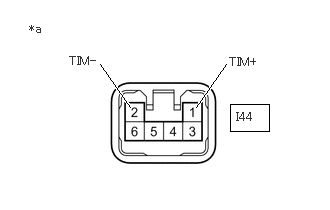
| *a | Component without harness connected (Tilt Motor) |
Apply 12 V battery voltage to the tilt motor connector. Then check the steering wheel tilt operation.
- OK:
-
Tester Connection Specified Condition Click Location & Routing(I44)Location & Routingewd_type=routing;type=c;code=I44
·12 V battery positive (+) lead → Terminal I44-2 (TIM-)
·12 V battery negative (-) lead → Terminal I44-1 (TIM+)
The steering wheel tilts down. ·12 V battery positive (+) lead → Terminal I44-1 (TIM+)
·12 V battery negative (-) lead → Terminal I44-2 (TIM-)
The steering wheel tilts up.
2.INSPECT TELESCOPIC MOTOR
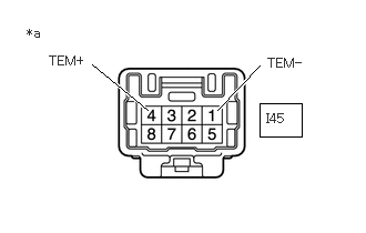
| *a | Component without harness connected (Telescopic Motor) |
Apply 12 V battery voltage to the telescopic motor connector. Then check the steering column telescopic operation.
- OK:
-
Tester Connection Specified Condition Click Location & Routing(I45)Location & Routingewd_type=routing;type=c;code=I45
·12 V battery positive (+) lead → Terminal I45-4 (TEM+)
·12 V battery negative (-) lead → Terminal I45-1 (TEM-)
The steering column contracts. ·12 V battery positive (+) lead → Terminal I45-1 (TEM-)
·12 V battery negative (-) lead → Terminal I45-4 (TEM+)
The steering column extends.
45250 3.INSPECT STEERING COLUMN ASSEMBLY
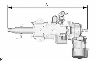
Measure the length of the steering main shaft.
- Standard length (A):
-
412.7 to 472.7 mm (1.36 to 1.55 ft.)
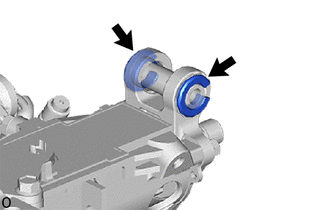
Check that the 2 bushings are securely installed to the steering column assembly.
- HINT:
-
If the bushings are deformed, missing or damaged, replace the steering column assembly with a new one.