STEERING COLUMN STEERING PAD SWITCH INSPECTION
PROCEDURE

 84250A 1.INSPECT STEERING PAD SWITCH ASSEMBLY
for Type A:
Measure the resistance according to the value(s) in the table below.
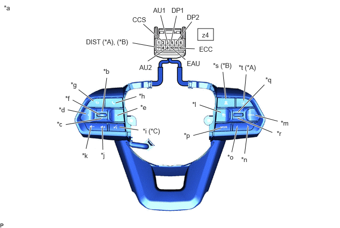
| *A | w/ Lane Departure Alert System | *B | w/ ACC Switch |
| *C | w/ Voice Switch | - | - |
| *a | Component without harness connected (Steering Pad Switch Assembly) |
*b | Up |
| *c | Down | *d | Left |
| *e | Right | *f | Enter |
| *g | Back | *h | Tel |
| *i | Voice | *j | Volume+ |
| *k | Volume- | *l | Main |
| *m | Cancel | *n | Seek+ |
| *o | Seek- | *p | MODE |
| *q | +RES | *r | -SET |
| *s | ACC | *t | Lane Departure Alert |
- Standard Resistance:
-
Tester Connection Condition Specified Condition *A: w/ Lane Departure Alert System
*B: w/ ACC Switch
*C: w/ Voice Switch
Click Location & Routing(z4)Location & Routingewd_type=routing;type=c;code=z4
z4-3 (AU1) -z4-10 (EAU) No switch pushed 95 to 105 kΩ Seek+ switch pushed Below 2.5 Ω Seek- switch pushed 313 to 345 Ω Volume+ switch pushed 950 to 1050 Ω Volume- switch pushed 2955 to 3265 Ω z4-9 (AU2) - z4-10 (EAU) No switch pushed 95 to 105 kΩ MODE switch pushed Below 2.5 Ω Tel switch pushed 950 to 1050 Ω Voice switch pushed (*C) 2955 to 3265 Ω z4-4 (DP1) - z4-10 (EAU) No switch pushed 95 to 105 kΩ Enter switch pushed Below 2.5 Ω Back switch pushed 313 to 345 Ω z4-5 (DP2) - z4-10 (EAU) No switch pushed 95 to 105 kΩ Left switch pushed Below 2.5 Ω Up switch pushed 313 to 345 Ω Down switch pushed 950 to 1050 Ω Right switch pushed 2955 to 3265 Ω z4-2 (CCS) - z4-12 (ECC) No switch pushed 1 MΩ or higher Main switch pushed Below 2.5 Ω Cancel switch pushed 228 to 252 Ω +RES switch pushed 599 to 661 Ω -SET switch pushed 1463 to 1617 Ω z4-8 (DIST) - z4-12 (ECC) No switch pushed 1 MΩ or higher ACC switch pushed (*B) Below 2.5 Ω Lane departure alert switch pushed (*A) 228 to 252 Ω
- HINT:
-
If the result is not as specified, replace the steering pad switch assembly.
for Type B:
Measure the resistance according to the value(s) in the table below.
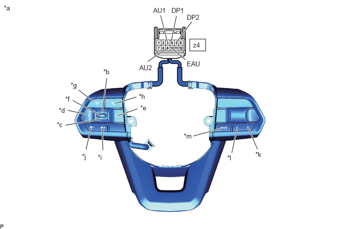
| *a | Component without harness connected (Steering Pad Switch Assembly) |
*b | Up |
| *c | Down | *d | Left |
| *e | Right | *f | Enter |
| *g | Back | *h | Tel |
| *i | Volume+ | *j | Volume- |
| *k | Seek+ | *l | Seek- |
| *m | MODE | - | - |
- Standard Resistance:
-
Tester Connection Condition Specified Condition Click Location & Routing(z4)Location & Routingewd_type=routing;type=c;code=z4
Click Connector(z4)Instrument Panel>other>Steering Pad Switch Assembly , Multiplex Network Steering Computer (Steering Wheel Assembly)ewd_type=component;type=c;code=z4;pinno=3,10,9,4,5
z4-3 (AU1) -z4-10 (EAU) No switch pushed 95 to 105 kΩ Seek+ switch pushed Below 2.5 Ω Seek- switch pushed 313 to 345 Ω Volume+ switch pushed 950 to 1050 Ω Volume- switch pushed 2955 to 3265 Ω z4-9 (AU2) - z4-10 (EAU) No switch pushed 95 to 105 kΩ MODE switch pushed Below 2.5 Ω Tel switch pushed 950 to 1050 Ω z4-4 (DP1) - z4-10 (EAU) No switch pushed 95 to 105 kΩ Enter switch pushed Below 2.5 Ω Back switch pushed 313 to 345 Ω z4-5 (DP2) - z4-10 (EAU) No switch pushed 95 to 105 kΩ Left switch pushed Below 2.5 Ω Up switch pushed 313 to 345 Ω Down switch pushed 950 to 1050 Ω Right switch pushed 2955 to 3265 Ω
Check the illumination.
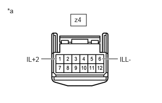
| *a | Component without harness connected (Steering Pad Switch Assembly) |
Apply battery voltage between the terminals of the switch, and check the illumination condition of the steering pad switch assembly.
- Standard:
-
Measurement Condition Specified Condition ·Battery positive (+) → z4-1 (IL+2)
·Battery negative (-) → z4-6 (ILL-)
Illuminates
- HINT:
-
If the result is not as specified, replace the steering pad switch assembly.