RM38G0E _55 Steering _100915 POWER ASSIST SYSTEMS _0469466 POWER STEERING SYSTEM(w/ Variable Flow Control Solenoid Valve) U
POWER ASSIST SYSTEMS POWER STEERING SYSTEM(w/ Variable Flow Control Solenoid Valve) TERMINALS OF ECU
CHECK POWER STEERING ECU ASSEMBLY
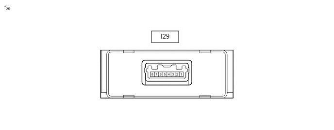
3.25,0.667 3.833,0.917 0.583,0.25 0.083,0.083 0.396,0.281 0.313,0.198 10 false *a 3.448,0.698 3.927,0.948 0.479,0.25 10 false I29
| *a | Component with harness connected (Power Steering ECU Assembly) |
- | - |
a.
Measure the voltage and resistance according to the value(s) in the table below.
- NOTICE:
-
When the power steering warning light is illuminated due to a malfunction, the fail-safe function may cause the voltage of the power steering ECU with motor assembly terminals to become 0 V.
- Standard:
-
Terminal No. (Symbol) Terminal Description Condition Specified Condition I29-3 (GND) - Body ground Ground Always Below 1 Ω I29-2 (CANL) - I29-1 (CANH) CAN communication Ignition switch off 54 to 69 Ω I29-5 (IG) - I29-3 (GND) IG power supply Ignition switch ON 11 to 14 V I29-7 (SOF+) - I29-8 (SOF-) Power steering solenoid valve signal ·Engine idling
·Steering wheel turned to right or left
Pulse generation
CHECK POWER STEERING ECU WITH MOTOR ASSEMBLY
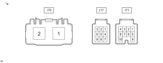
1.938,0.333 2.354,0.583 0.417,0.25 4.25,0.333 4.667,0.583 0.417,0.25 5.365,0.333 5.781,0.583 0.417,0.25 2.073,0.365 2.531,0.563 0.458,0.198 10 false I70 0.24,0.083 0.698,0.281 0.458,0.198 10 false *a 4.344,0.365 4.625,0.552 0.281,0.188 10 false z17 5.49,0.365 5.948,0.563 0.458,0.198 10 false I71
| *a | Component without harness connected (Power Steering ECU with Motor Assembly) |
- | - |
a.
Measure the voltage and resistance according to the value(s) in the table below.
- NOTICE:
-
When the power steering warning light is illuminated due to a malfunction, the fail-safe function may cause the voltage of the power steering ECU with motor assembly terminals to become 0 V.
| Terminal No. (Symbol) | Terminal Description | Condition | Specified Condition |
|---|---|---|---|
|
*1: w/o Stop and Start System *2: w/ Stop and Start System |
|||
| I71-1 (IG) - Body ground | IG power source | Ignition switch ON | 8 to 16 V*1 10.5 to 16 V*2 |
| I71-7 (CANH) - I71-8 (CANL) | CAN communication line | Ignition switch off | 54 to 69 Ω |
| z17-1 (TRQ2) - z17-2 (TRQG2) | Torque sensor 2 signal | Engine running and steering wheel not being turned (without load) | 2.3 to 2.7 V |
| Engine running and steering wheel being turned to the right with vehicle stopped | 1.2 to 2.5 V | ||
| Engine running and steering wheel being turned to the left with vehicle stopped | 2.5 to 3.8 V | ||
| z17-2 (TRQG2) - Body ground | Torque sensor 2 ground | Always | Below 1 Ω |
| z17-3 (TRQV2) - z17-2 (TRQG2) | Torque sensor 2 voltage source | Ignition switch ON | 4.5 to 5.5 V |
| z17-7 (TRQV1) - z17-8 (TRQG1) | Torque sensor 1 voltage source | Ignition switch ON | 4.5 to 5.5 V |
| z17-8 (TRQG1) - Body ground | Torque sensor 1 ground | Always | Below 1 Ω |
| z17-9 (TRQ1) - z17-8 (TRQG1) | Torque sensor signal | Engine running and steering wheel not being turned (without load) | 2.3 to 2.7 V |
| Engine running and steering wheel being turned to the right with vehicle stopped | 2.5 to 3.8 V | ||
| Engine running and steering wheel being turned to the left with vehicle stopped | 1.2 to 2.5 V | ||
| I70-1 (PIG) - Body ground | Power source | Ignition switch ON | 9 to 16 V |
| I70-2 (PGND) - Body ground | Power ground | Always | Below 1 Ω |