RM38G0E _55 Steering _100915 POWER ASSIST SYSTEMS _0469466 POWER STEERING SYSTEM(w/ Variable Flow Control Solenoid Valve) J
POWER ASSIST SYSTEMS POWER STEERING SYSTEM(w/ Variable Flow Control Solenoid Valve) IG Power Source Circuit
DESCRIPTION
When the ignition switch is turned to ON, the IG power source circuit supplies positive (+) voltage to the power steering ECU assembly.
WIRING DIAGRAM
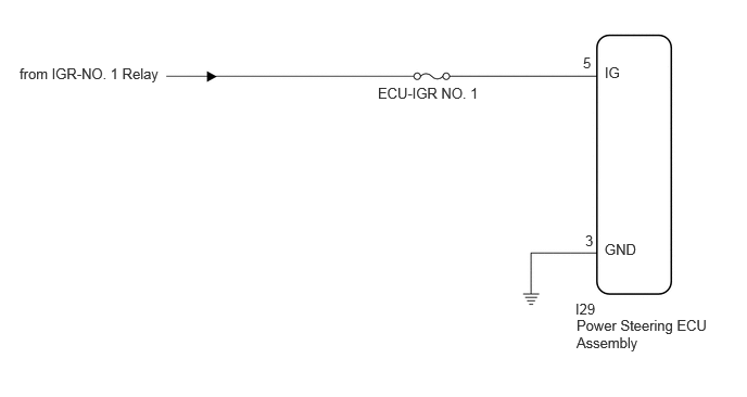
0.188,0.625 1.781,0.844 1.594,0.219 10 false from IGR-NO. 1 Relay 3.625,0.813 4.844,1.104 1.219,0.292 10 false ECU-IGR NO. 1 5.521,2.885 5.927,3.083 0.406,0.198 10 false I29 5.531,3.042 6.823,3.469 1.292,0.427 10 false Power Steering ECU Assembly 5.802,2.313 6.177,2.479 0.375,0.167 10 false GND 5.802,0.615 6.083,0.802 0.281,0.188 10 false IG 5.594,0.521 5.781,0.708 0.188,0.188 10 false 5 5.615,2.229 5.802,2.417 0.188,0.188 10 false 3
CAUTION / NOTICE / HINT
- NOTICE:
-
Inspect the fuses for circuits related to this system before performing the following inspection procedure.
PROCEDURE
1.CHECK HARNESS AND CONNECTOR (POWER STEERING ECU ASSEMBLY - BATTERY AND BODY GROUND)
a.
Disconnect the I29 power steering ECU assembly connector.
b.
Measure the voltage according to the value(s) in the table below.
- Standard Voltage:
-
Tester Connection Switch Condition Specified Condition Click Location & Routing(I29)Location & Routingewd_type=routing;type=c;code=I29
I29-5 (IG) - Body ground Ignition switch ON 11 to 14 V
c.
Measure the resistance according to the value(s) in the table below.
- Standard Resistance:
-
Tester Connection Condition Specified Condition Click Location & Routing(I29)Location & Routingewd_type=routing;type=c;code=I29
I29-3 (GND) - Body ground Always Below 1 Ω
- Result:
-
Proceed to OK NG
OK
GO TO POWER STEERING SYSTEM (PROBLEM SYMPTOMS TABLE)
NG
REPAIR OR REPLACE HARNESS OR CONNECTOR