V35A-FTS INTAKE / EXHAUST INTAKE AIR CONTROL VALVE INSPECTION
PROCEDURE

 17670B 1.INSPECT AIR BY-PASS VALVE ASSEMBLY (for Bank 2)
Check the operation.
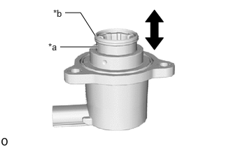
| *a | Plunger |
| *b | Plunger Seal |
When the plunger of the air by-pass valve assembly is pressed and released, check that the plunger quickly returns to its original position.
- NOTICE:
-
Make sure no foreign matter is stuck to the plunger seal of the air by-pass valve assembly and the plunger seal is not damaged.
If the plunger does not return to its original position, replace the air by-pass valve assembly.
Inspect the resistance.
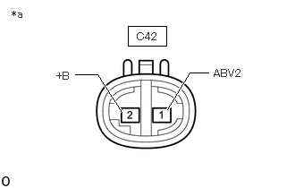
| *a | Component without harness connected (Air By-pass Valve Assembly) |
Measure the resistance according to the value(s) in the table below.
- Standard Resistance:
-
Tester Connection Condition Specified Condition Click Location & Routing(C42)Location & Routingewd_type=routing;type=c;code=C42
C42-1 (ABV2) - C42-2 (+B) 20°C (68°F) 8.6 to 9.6 Ω
If the result is not as specified, replace the air by-pass valve assembly.
17670B 2.INSPECT AIR BY-PASS VALVE ASSEMBLY (for Bank 1)
Check the operation.
| *a | Plunger |
| *b | Plunger Seal |
When the plunger of the air by-pass valve assembly is pressed and released, check that the plunger quickly returns to its original position.
- NOTICE:
-
Make sure no foreign matter is stuck to the plunger seal of the air by-pass valve assembly and the plunger seal is not damaged.
If the plunger does not return to its original position, replace the air by-pass valve assembly.
Inspect the resistance.
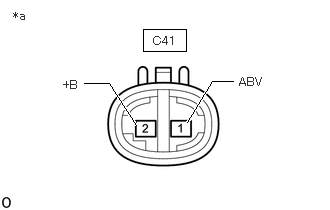
| *a | Component without harness connected (Air By-pass Valve Assembly) |
Measure the resistance according to the value(s) in the table below.
- Standard Resistance:
-
Tester Connection Condition Specified Condition Click Location & Routing(C41)Location & Routingewd_type=routing;type=c;code=C41
C41-1 (ABV) - C41-2 (+B) 20°C (68°F) 8.6 to 9.6 Ω
If the result is not as specified, replace the air by-pass valve assembly.