V35A-FTS INTAKE / EXHAUST TURBOCHARGER INSPECTION
PROCEDURE

 1.INSPECT TURBINE WITH VALVE HOUSING SUB-ASSEMBLY
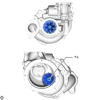
| *a | Center of Exhaust Side Turbine |
Check if the compressor side impeller and exhaust side turbine are damaged or defective.
- HINT:
-
Wearing on the center of the exhaust side turbine is not a problem.
Move the rod by hand and check whether the waste gate valve is stuck.
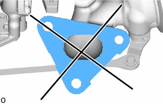
Using a straightedge and feeler gauge, measure the warpage of the turbine with valve housing sub-assembly installation surface.
- Standard warpage:
-
0.20 mm (0.00787 in.)
If the result is not as specified, replace the turbocharger sub-assembly.
When the waste gate valve is fully closed, using a feeler gauge, measure the clearance between the waste gate valve and the contact surface of the turbine with valve housing sub-assembly waste gate valve port.
- Standard clearance:
-
0.50 mm (0.0197 in.)
If the result is not as specified, replace the turbocharger sub-assembly.
2.INSPECT TURBINE SHAFT
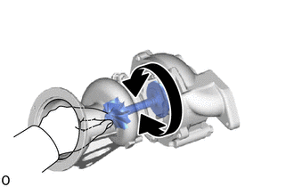
Grasp the compressor wheel nut with your fingers, and then turn the nut. Check that the compressor wheel rotates smoothly.
- NOTICE:
-
If the compressor wheel does not rotate smoothly and there is interference between the turbine wheel and turbine with valve housing sub-assembly, replace the turbocharger sub-assembly at the same time.
- HINT:
-
If the compressor wheel does not rotate smoothly, replace the turbocharger sub-assembly.
Check the turbine shaft in the axial direction.
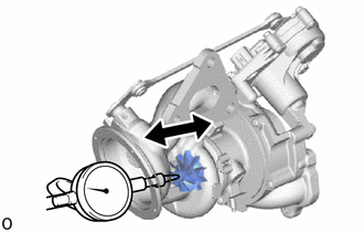
Set a dial indicator to the outlet side of the turbine shaft.
Move the turbine shaft in the axial direction and check for looseness.
- Standard:
-
0.10 mm (0.00394 in.) or less
If the result is not as specified, replace the turbocharger sub-assembly.
3.INSPECT TURBOCHARGER WASTE GATE VALVE CONTROL ACTUATOR
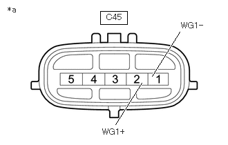
| *a | Component without harness connected (No. 1 Turbocharger Sub-assembly) |
for Bank 2:
Measure the resistance according to the value(s) in the table below.
- Standard Resistance:
-
Tester Connection Condition Specified Condition Click Location & Routing(C45)Location & Routingewd_type=routing;type=c;code=C45
C45-1 (WG1-) - C45-2 (WG1+) 20°C (68°F) 1 to 100 Ω
If the result is not as specified, replace the No. 1 turbocharger sub-assembly.
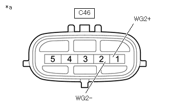
| *a | Component without harness connected (No. 2 Turbocharger Sub-assembly) |
for Bank 1:
Measure the resistance according to the value(s) in the table below.
- Standard Resistance:
-
Tester Connection Condition Specified Condition Click Location & Routing(C46)Location & Routingewd_type=routing;type=c;code=C46
C46-1 (WG2+) - C46-2 (WG2-) 20°C (68°F) 1 to 100 Ω
If the result is not as specified, replace the No. 2 turbocharger sub-assembly.