1GR-FE EMISSION CONTROL EMISSION CONTROL SYSTEM ON-VEHICLE INSPECTION
CAUTION / NOTICE / HINT
- CAUTION:
-
-
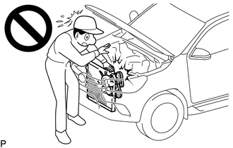
To prevent injury due to contact with an operating fan and generator V-belt or cooling fan, keep your hands and clothing away from the fan and generator V-belt and cooling fans when working in the engine compartment with the engine running.
PROCEDURE

 1.INSPECT FUEL CUT-OFF RPM
- CAUTION:
-
To prevent injury due to contact with an operating fan and generator V-belt or cooling fan, keep your hands and clothing away from the fan and generator V-belt and cooling fans when working in the engine compartment with the engine running.
Start and warm up the engine.
Increase the engine speed to at least 3500 rpm.
Use a sound scope to check for fuel injector assembly operation noise.
Check that when the accelerator pedal is released, the fuel injector assembly operation noise stops momentarily and then resumes.
- Standard:
-
Item Specified Condition Fuel cut permission engine speed 2500 rpm or higher Fuel injection restart engine speed 1200 rpm
If the result is not as specified, check the fuel injector assembly, wiring and ECM.
2.VISUALLY INSPECT HOSES, CONNECTIONS AND GASKETS
Visually check that the hoses, connections and gaskets have no cracks, leaks or damage.
- NOTICE:
-
·
Detachment or other problems with the engine oil level dipstick, oil filler cap sub-assembly, PCV hose and other components may cause the engine to run improperly.
·Air suction caused by disconnections, looseness or cracks in the parts of the air induction system between the throttle body and cylinder head sub-assembly will cause engine failure or engine malfunctions.
If the result is not as specified, replace parts as necessary.
77001A 3.CHECK FUEL TANK ASSEMBLY
Visually check for deformation, cracks or fuel leakage.
25860 4.CHECK PURGE VSV (NO. 1 VACUUM SWITCHING VALVE ASSEMBLY)
- CAUTION:
-
To prevent injury due to contact with an operating fan and generator V-belt or cooling fan, keep your hands and clothing away from the fan and generator V-belt and cooling fans when working in the engine compartment with the engine running.
Connect the GTS to the DLC3.
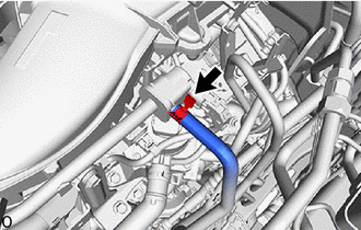
Slide the clamp and disconnect the fuel vapor feed hose (connected to the charcoal canister assembly) from the purge VSV (No. 1 vacuum switching valve assembly).
Start the engine and turn the GTS on.
- Powertrain > Engine > Active Test
-
Tester Display Activate the VSV for Evap Control - 50004 234 6
- OK:
-
Tester Operation Specified Condition VSV is OFF Purge VSV has no suction VSV is ON Purge VSV has suction
Connect the fuel vapor feed hose (connected to the canister) to the purge VSV (No. 1 vacuum switching valve assembly), and slide the clamp to secure the hose.
5.INSPECT SECONDARY AIR INJECTION SYSTEM OPERATION
Start the engine and warm it up.
Turn the ignition switch off.
Turn the ignition switch to ON.
Perform the secondary air injection system forced operation while the engine is idling.
- HINT:
-
When Manual Mode is selected, the GTS initialization (atmospheric pressure measurement) is performed automatically. The initialization takes 5 seconds. After the initialization, air pump assembly and emission control valve operation can be selected.
- Powertrain > Engine > Utility
-
Tester Display Secondary Air Injection Check - 50005 372 26
Start the engine.
Check that the air pump assembly (AIR PUMP), emission control valve (ASV 1 and ASV 2) and pressure in the secondary air injection system passage (PRESSURE) status displayed on the GTS match the conditions shown in the table below.
- Standard:
-
GTS Operation AIR PUMP ASV 1
ASV 2PRESSURE* AIR PUMP: ON, ASV 1: OPEN, ASV 2: OPEN ON ON 1 kPa or more [A] AIR PUMP: OFF, ASV 1: CLOSE, ASV 2: CLOSE OFF OFF Less than 2.5 kPa [B]
*: Average pumping pressure. The pressure should be 1 kPa or more when the secondary air injection system operates.
- Standard:
-
The pressures for [A] and [B] should differ by 1 kPa or more.
Turn the ignition switch off.
- NOTICE:
-
·
This Secondary Air Injection Check only allows technicians to operate the secondary air injection system for a maximum of 5 seconds.
Furthermore, the check can only be performed up to 4 times per trip. If the test is repeated, intervals of at least 30 seconds are required between checks.
While secondary air injection system operation using the GTS is prohibited, the GTS display indicates the prohibition (WAIT or ERROR).
If ERROR is displayed on the GTS during the test, stop the engine for 10 minutes, and then try again.
·Performing the Secondary Air Injection Check repeatedly may cause damage to the secondary air injection system. If necessary, leave an interval of several minutes between System Check operations to prevent the system from overheating.
·When performing the Secondary Air Injection Check operation after the battery cable has been reconnected, wait for 7 minutes with the ignition switch turned to ON or the engine running.
·Turn the ignition switch off when the Secondary Air Injection Check operation finishes.