RM38G0E _51 Engine / Hybrid System _101531 1GR-FE EMISSION CONTROL _0470512 PURGE VALVE G
1GR-FE EMISSION CONTROL PURGE VALVE INSPECTION
PROCEDURE

 25860 1.INSPECT PURGE VSV (NO. 1 VACUUM SWITCHING VALVE ASSEMBLY)
a.
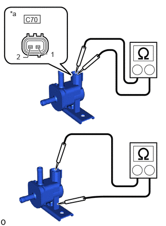
0.5,0.313 0.833,0.479 0.333,0.167 0.979,1.115 0.854,1.115 0.854,1.115 0.781,0.969 true 0.625,0.99 0.573,1.188 0.573,1.188 0.479,1.188 true 0.208,0.198 0.521,0.396 0.313,0.198 10 false *a 1.052,1.042 1.365,1.24 0.313,0.198 10 false 1 0.344,1.094 0.656,1.292 0.313,0.198 10 false 2 0.531,0.323 0.865,0.49 0.333,0.167 10 false C70
| *a | Component without harness connected (Purge VSV (No. 1 Vacuum Switching Valve Assembly)) |
Measure the resistance according to the value(s) in the table below.
- Standard Resistance:
-
Tester Connection Condition Specified Condition Click Location & Routing(C70)Location & Routingewd_type=routing;type=c;code=C70
C70-1 - C70-2 20°C (68°F) 23 to 26 Ω C70-1 - Body ground Always 10 MΩ or higher C70-2 - Body ground
If the result is not as specified, replace the purge VSV (No. 1 vacuum switching valve assembly).
b.
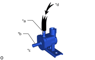
Check the operation of the purge VSV (No. 1 vacuum switching valve assembly).
i.
0.833,1.229 1.021,1.229 1.021,1.229 1.271,1.594 true 0.99,0.74 1.177,0.74 1.177,0.74 1.594,1.198 true 0.646,1.146 0.844,1.344 0.198,0.198 10 false *b 0.99,1.75 1.188,1.938 0.198,0.188 10 false *c 2,0.083 2.208,0.292 0.208,0.208 10 false *d 0.802,0.677 1,0.875 0.198,0.198 10 false *a
| *a | Port E |
| *b | Port F |
| *c | Does not flow |
| *d | Air |
Check that air does not flow from port F when air is applied to port E.
ii.
0.615,0.583 0.76,0.583 0.76,0.583 1.115,1.135 true 0.385,1.083 0.531,1.083 0.531,1.083 0.781,1.615 true 0.417,0.479 0.615,0.677 0.198,0.198 10 false *a 1.552,0.063 1.75,0.26 0.198,0.198 10 false *c 0.198,1.01 0.396,1.208 0.198,0.198 10 false *b
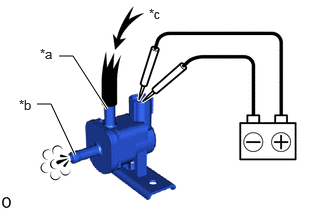
| *a | Port F |
| *b | Port E |
| *c | Air |
Apply battery voltage to the connector and check the purge VSV operation.
- OK:
-
Measurement Condition Specified Condition Battery positive (+) - C70-1
Battery negative (-) - C70-2Air flows from port E to port F
If the result is not as specified, replace the purge VSV (No. 1 vacuum switching valve assembly).