RM38G0E _56 Audio / Visual / Telematics _100728 PARK ASSIST / MONITORING _0469675 MULTI-TERRAIN MONITOR SYSTEM U
PARK ASSIST / MONITORING MULTI-TERRAIN MONITOR SYSTEM TERMINALS OF ECU
PARKING ASSIST ECU
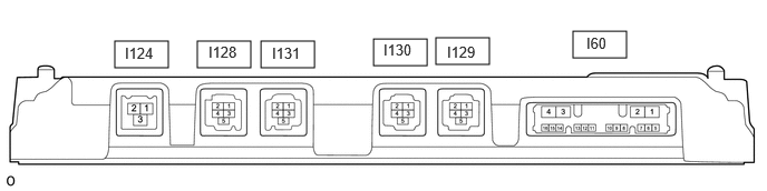
5.354,0.292 5.854,0.542 0.5,0.25 4.073,0.354 4.573,0.604 0.5,0.25 1.073,0.385 1.573,0.635 0.5,0.25 2.438,0.385 2.938,0.635 0.5,0.25 3.49,0.365 3.99,0.615 0.5,0.25 1.844,0.385 2.344,0.635 0.5,0.25 5.479,0.323 5.938,0.521 0.458,0.198 10 false I60 1.167,0.417 1.625,0.615 0.458,0.198 10 false I124 4.177,0.406 4.635,0.604 0.458,0.198 10 false I129 2.542,0.417 3,0.615 0.458,0.198 10 false I131 3.583,0.385 4.042,0.583 0.458,0.198 10 false I130 1.948,0.406 2.406,0.604 0.458,0.198 10 false I128
a.
Disconnect the I60 parking assist ECU connector.
b.
Measure the voltage and resistance according to the value(s) in the table below.
| Terminal No. (Symbol) | Terminal Description | Condition | Specified Condition |
|---|---|---|---|
| I60-1 (+B) - I60-4 (GND) | Power source signal | Always | 11 to 14 V |
| I60-2 (ACC) - I60-4 (GND) | ACC power source signal | Ignition switch ACC | 11 to 14 V |
| Ignition switch off | Below 1 V | ||
| I60-3 (IG) - I60-4 (GND) | IG power source signal | Ignition switch ON | 11 to 14 V |
| Ignition switch off | Below 1 V | ||
| I60-4 (GND) - Body ground | Ground | Always | Below 1 Ω |
c.
Reconnect the I60 parking assist ECU connector.
d.
Measure the voltage and resistance according to the value(s) in the table below.
| Terminal No. (Symbol) | Terminal Description | Condition | Specified Condition |
|---|---|---|---|
| I60-11 (CANH) | CAN communication line | - | - |
| I60-12 (CANL) | CAN communication line | - | - |
| I60-13 (RSW+) - I60-4 (GND) | Terminal required by law | Panoramic image being displayed | 0 to 2 V |
| Panoramic image not being displayed | 5.5 to 7.05 V | ||
| I60-15 (BLSW) - I60-4 (GND) | Multi-terrain monitor switch (trip switch) switch signal | Ignition switch ON, multi-terrain monitor switch (trip switch) switch off | 5.5 to 6.5 V |
| Ignition switch ON, multi-terrain monitor switch (trip switch) switch on | Below 1 V | ||
| I124-1 (GVO+) | Video signal (Digital) | - | - |
| I124-2 (GVO-) | Video signal (Digital) | - | - |
| I124-3 (GVG1) | Shield ground | - | - |
| I128-1 (BGND) - Body ground | Front television camera assembly display ground | Always | Below 1 Ω |
| I128-2 (BCB+) - I128-1 (BGND) | Power source to front television camera | Ignition switch ON | 7 to 8 V |
| I128-3 (BCV-) | Front television camera assembly display ground | - | - |
| I128-4 (BCV+) | Front television camera assembly display signal input | - | - |
| I128-5 (SGND) - Body ground | Front television camera assembly ground (shield) | Always | Below 1 Ω |
| I130-1 (LGND) - Body ground | Side television camera assembly LH ground | Always | Below 1 Ω |
| I130-2 (LCB+) - I130-1 (LGND) | Power source to side television camera assembly LH | Ignition switch ON | 7 to 8 V |
| I130-3 (LCV-) | Side television camera assembly LH display ground | - | - |
| I130-4 (LCV+) | Side television camera assembly LH display signal input | - | - |
| I130-5 (SGND) - Body ground | Side television camera assembly LH ground (shield) | Always | Below 1 Ω |
| I131-1 (CGND) - Body ground | Rear television camera assembly ground | Always | Below 1 Ω |
| I131-2 (CB+) - I131-1 (CGND) | Power source to rear television camera assembly | Ignition switch ON | 7 to 8 V |
| I131-3 (CV-) | Rear television camera assembly display ground | - | - |
| I131-4 (CV+) | Rear television camera assembly display signal input | - | - |
| I131-5 (SGND) - Body ground | Rear television camera assembly ground (shield) | Always | Below 1 Ω |
| I129-1 (RGND) - Body ground | Side television camera assembly RH display ground | Always | Below 1 Ω |
| I129-2 (RCB+) - I129-1 (RGND) | Power source to side television camera assembly RH | Ignition switch ON | 7 to 8 V |
| I129-3 (RCV-) | Side television camera assembly RH display ground | - | - |
| I129-4 (RCV+) | Side television camera assembly RH display signal input | - | - |
| I129-5 (SGND) - Body ground | Side television camera assembly RH ground (shield) | Always | Below 1 Ω |
MULTI-DISPLAY ASSEMBLY
w/ Navigation System
Click hereAudio / Visual / Telematics>NAVIGATION / MULTI INFO DISPLAY>NAVIGATION SYSTEM>TERMINALS OF ECU
w/ Audio and Visual System