RM38G0E _53 Suspension _100546 SUSPENSION CONTROL _0470891 ELECTRONIC-KINETIC DYNAMIC SUSPENSION SYSTEM U
SUSPENSION CONTROL ELECTRONIC-KINETIC DYNAMIC SUSPENSION SYSTEM TERMINALS OF ECU
STABILIZER CONTROL ECU
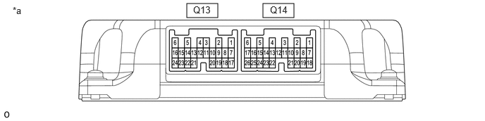
2.76,0.052 3.219,0.26 0.458,0.208 3.885,0.052 4.344,0.26 0.458,0.208 0.188,0.073 0.448,0.271 0.26,0.198 10 false *a 2.854,0.063 3.208,0.229 0.354,0.167 10 false Q13 3.99,0.063 4.344,0.229 0.354,0.167 10 false Q14
| *a | Component with harness connected (Stabilizer Control ECU) |
- | - |
| Terminal No. | Symbol | Terminal Description |
|---|---|---|
| Q13-1 | RLO- | Rear lower chamber switch valve downstream output signal |
| Q13-2 | RLO+ | Rear lower chamber switch valve upstream output signal |
| Q13-5 | RUP- | Rear upper chamber switch valve downstream output signal |
| Q13-6 | RUP+ | Rear upper chamber switch valve upstream output signal |
| Q14-1 | IGB | ECU power supply |
| Q14-2 | FNC+ | Front normal close switch valve upstream output signal |
| Q14-3 | FNC- | Front normal close switch valve downstream output signal |
| Q14-4 | GND | GND |
| Q14-5 | FNO+ | Front normal open switch valve upstream output signal |
| Q14-6 | FNO- | Front normal open switch valve downstream output signal |
| Q14-7 | CANL | CAN communication Lo signal |
| Q14-8 | CANH | CAN communication Hi signal |
a.
Measure the voltage and resistance according to the value(s) in the table below.
| Terminal No. (Symbol) | Condition | Specified Condition |
|---|---|---|
| Q14-1 (IGB) - Body ground | Ignition switch ON | 10.5 to 15.5 V |
| Q14-4 (GND) - Body ground | Always | Below 1 Ω |
| Q14-7 (CANL) - Q14-8 (CANH) |
·
Ignition switch off
·
Cable disconnected from negative (-) battery terminal |
54 to 69 Ω |