SUSPENSION CONTROL FRONT ACCELERATION SENSOR INSPECTION
PROCEDURE

 89191A 1.INSPECT ACCELERATION SENSOR (for LHD)
Connect 3 1.5 V dry cell batteries in series.
for Driver Side:
Connect a positive (+) lead from the batteries to S10 terminal 3 (SBG) and a negative (-) lead to S10 terminal 2 (SGG).
for Passenger Side:
Connect a positive (+) lead from the batteries to Q15 terminal 3 (SBG) and a negative (-) lead to Q15 terminal 2 (SGG).
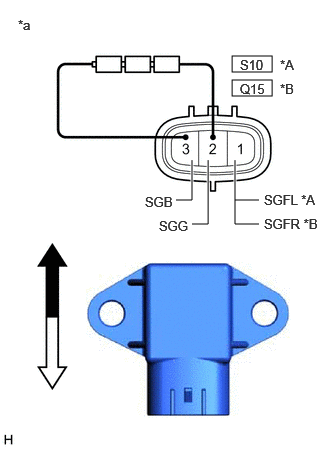
| *A | for Driver Side |
| *B | for Passenger Side |
| *a | Component without harness connected (Acceleration Sensor) |

|
Top |

|
Bottom |
Measure the voltage according to the value(s) in the table below.
- Standard Voltage:
-
for Driver Side: Tester Connection Condition Specified Condition Click Location & Routing(S10)Location & Routingewd_type=routing;type=c;code=S10
Click Connector(S10)Instrument Panel>No. 2 Floor Wire>Acceleration Sensor LHewd_type=component;type=c;code=S10;pinno=1,2
S10-1 (SGFL) - S10-2 (SGG) Sensor stationary Approx. 2.0 to 2.5 V Sensor vibrating vertically Changes between approx. 0.9 and 3.6 V
-
for Passenger Side: Tester Connection Condition Specified Condition Click Location & Routing(Q15)Location & Routingewd_type=routing;type=c;code=Q15
Click Connector(Q15)Instrument Panel>Floor Wire / No. 1 Cooler Wiring Harness Sub-Assembly>Acceleration Sensor RHewd_type=component;type=c;code=Q15;pinno=1,2
Q15-1 (SGFR) - Q15-2 (SGG) Sensor stationary Approx. 2.0 to 2.5 V Sensor vibrating vertically Changes between approx. 0.9 and 3.6 V
- NOTICE:
-
·
Do not apply a voltage of more than 6 V.
·Do not drop the acceleration sensor. If it is dropped, replace it with a new one.
·Never place the acceleration sensor upside down.
- HINT:
-
When the acceleration sensor is tilted, it may output a different value.
If the result is not as specified, replace the acceleration sensor.
89191A 2.INSPECT ACCELERATION SENSOR (for RHD)
Connect 3 1.5 V dry cell batteries in series.
for Driver Side:
Connect a positive (+) lead from the batteries to Q15 terminal 3 (SBG) and a negative (-) lead to Q15 terminal 2 (SGG).
for Passenger Side:
Connect a positive (+) lead from the batteries to S10 terminal 3 (SBG) and a negative (-) lead to S10 terminal 2 (SGG).
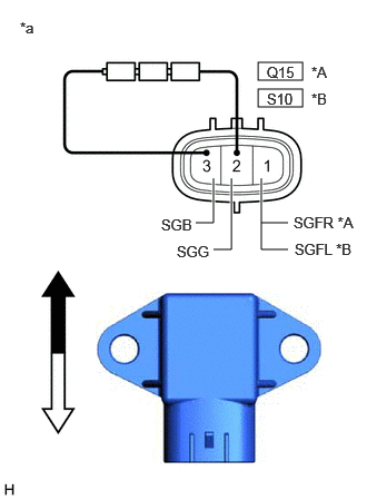
| *A | for Driver Side |
| *B | for Passenger Side |
| *a | Component without harness connected (Acceleration Sensor) |
|
|
Top |
|
|
Bottom |
Measure the voltage according to the value(s) in the table below.
- Standard Voltage:
-
for Driver Side: Tester Connection Condition Specified Condition Click Location & Routing(Q15)Location & Routingewd_type=routing;type=c;code=Q15
Click Connector(Q15)Instrument Panel>Floor Wire / No. 1 Cooler Wiring Harness Sub-Assembly>Acceleration Sensor RHewd_type=component;type=c;code=Q15;pinno=1,2
Q15-1 (SGFR) - Q15-2 (SGG) Sensor stationary Approx. 2.0 to 2.5 V Sensor vibrating vertically Changes between approx. 0.9 and 3.6 V
-
for Passenger Side: Tester Connection Condition Specified Condition Click Location & Routing(S10)Location & Routingewd_type=routing;type=c;code=S10
Click Connector(S10)Instrument Panel>No. 2 Floor Wire>Acceleration Sensor LHewd_type=component;type=c;code=S10;pinno=1,2
S10-1 (SGFL) - S10-2 (SGG) Sensor stationary Approx. 2.0 to 2.5 V Sensor vibrating vertically Changes between approx. 0.9 and 3.6 V
- NOTICE:
-
·
Do not apply a voltage of more than 6 V.
·Do not drop the acceleration sensor. If it is dropped, replace it with a new one.
·Never place the acceleration sensor upside down.
- HINT:
-
When the acceleration sensor is tilted, it may output a different value.
If the result is not as specified, replace the acceleration sensor.