DRIVE SHAFT / PROPELLER SHAFT FRONT DRIVE SHAFT ASSEMBLY INSPECTION
CAUTION / NOTICE / HINT
- NOTICE:
-
·
When using a vise, place aluminum plates between the part and vise.
·When using a vise, do not overtighten it.
PROCEDURE

 1.INSPECT FRONT DRIVE SHAFT ASSEMBLY
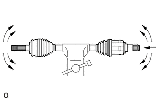
Check that there is no excessive play in the radial direction of the inboard joint and outboard joint.
Check that the inboard joint slides smoothly in the thrust direction.
Check that there is no excessive play in the radial direction of the inboard joint.
Check that the inboard joint boot and outboard joint boot are not cracked or damaged, and no grease is leaking out.
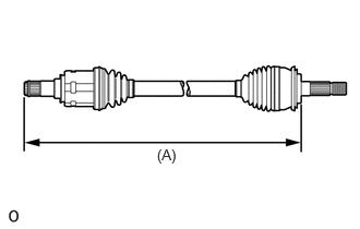
Check that the inboard joint boot and outboard joint boot are not stretched or contracted when the front drive shaft assembly is at the standard length.
- Dimension (A) (w/ Differential Lock):
-
for LH Side 610.27 mm (2.00 ft.) for RH Side 658.27 mm (2.16 ft.)
- Dimension (A) (w/o Differential Lock):
-
for LH Side 589.17 mm (1.93 ft.) for RH Side 637.17 mm (2.09 ft.)
- NOTICE:
-
Keep the front drive shaft assembly level during inspection.
If the inboard joint boot and outboard joint boot are stretched or contracted, correct them.