RM38G0E _56 Audio / Visual / Telematics _100606 AUDIO / VIDEO _0467496 AUDIO AND VISUAL SYSTEM(for Radio and Display Type, for 12.3 Inch Display) J
AUDIO / VIDEO AUDIO AND VISUAL SYSTEM(for Radio and Display Type, for 12.3 Inch Display) Voice Guidance does not Function
WIRING DIAGRAM
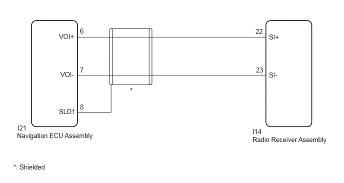
1.229,0.677 1.771,0.917 0.542,0.24 10 false VOI+ 1.229,2.24 1.771,2.479 0.542,0.24 10 false SLD1 0.365,2.583 0.906,2.823 0.542,0.24 10 false I21 0.354,2.74 2.063,3.052 1.708,0.313 10 false Navigation ECU Assembly 5.26,2.656 5.802,2.896 0.542,0.24 10 false I14 5.26,2.823 6.896,3.063 1.635,0.24 10 false Radio Receiver Assembly 5.604,0.688 6.146,0.927 0.542,0.24 10 false SI+ 5.323,0.573 5.865,0.813 0.542,0.24 10 false 22 5.333,1.375 5.875,1.615 0.542,0.24 10 false 23 1.667,0.563 2.208,0.802 0.542,0.24 10 false 6 1.667,1.375 2.208,1.615 0.542,0.24 10 false 7 1.667,2.146 2.208,2.385 0.542,0.24 10 false 8 1.26,1.469 1.802,1.708 0.542,0.24 10 false VOI- 5.604,1.479 6.146,1.719 0.542,0.24 10 false SI- 2.708,1.802 3.385,2.125 0.677,0.323 10 false * 0.281,3.396 1.135,3.646 0.854,0.25 10 false *: Shielded
PROCEDURE
1.CHECK VOICE GUIDANCE SETTING
a.
Check that the voice guidance setting is not off.
- OK:
-
Voice guidance setting is not off.
- Result:
-
Proceed to OK NG
OK
2.CHECK HARNESS AND CONNECTOR (RADIO RECEIVER ASSEMBLY - NAVIGATION ECU ASSEMBLY)
NG
CHANGE VOICE GUIDANCE SETTING TO ON
2.CHECK HARNESS AND CONNECTOR (RADIO RECEIVER ASSEMBLY - NAVIGATION ECU ASSEMBLY)
a.
Disconnect the I14 radio receiver assembly connector.
b.
Disconnect the I21 navigation ECU assembly connector.
c.
Measure the resistance according to the value(s) in the table below.
- Standard Resistance:
-
Tester Connection Condition Specified Condition Click Location & Routing(I14,I21)Location & Routingewd_type=routing;type=c,c;code=I14,I21
I14-22 (SI+) - I21-6 (VOI+) Always Below 1 Ω I14-23 (SI-) - I21-7 (VOI-) Always Below 1 Ω I14-22 (SI+) or I21-6 (VOI+) - Body ground Always 10 kΩ or higher I14-23 (SI-) or I21-7 (VOI-) - Body ground Always 10 kΩ or higher I21-8 (SLD1) - Body ground Always 10 kΩ or higher
- Result:
-
Proceed to OK NG
OK
PROCEED TO NEXT SUSPECTED AREA SHOWN IN PROBLEM SYMPTOMS TABLE
NG
REPAIR OR REPLACE HARNESS OR CONNECTOR