AXLE AND DIFFERENTIAL FRONT DIFFERENTIAL LOCK POSITION SWITCH INSPECTION
PROCEDURE

 84546 1.INSPECT NO. 1 4 WHEEL DRIVE POSITION SWITCH
Connect 3 new dry-cell batteries (1.5 V each) in series.
Prepare a magnet or equivalent tool.
Connect a positive (+) lead from the batteries to terminal 1 (VCC) and a negative (-) lead to terminal 3 (GND).
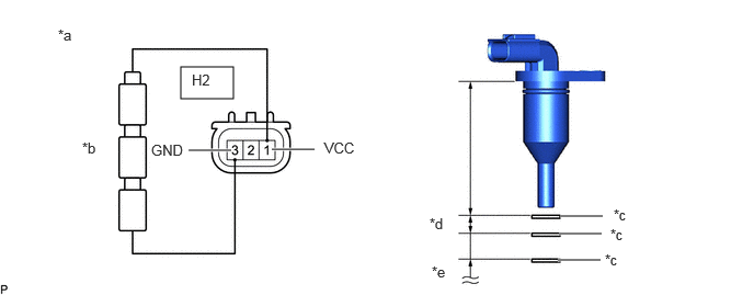
| *a | Component without harness connected (No. 1 4 Wheel Drive Position Switch) |
*b | Dry Cell Battery |
| *c | Magnet or Equivalent tool | *d | 60.81 to 62.31 mm (2.400 to 2.453 in.) |
| *e | 63.34 mm (2.494 in.) or more | - | - |
Place a magnet or equivalent tool at a distance between A and B and measure the voltage between each terminal.
- Standard Voltage (Combined Dry-cell Battery Voltage of 4.5 V):
-
Tester Connection Condition Specified Condition Click Location & Routing(H2)Location & Routingewd_type=routing;type=c;code=H2
Click Connector(H2)Engine Compartment>Differential Wire>Differential Position Switch (Front Differential Assembly)ewd_type=component;type=c;code=H2;pinno=1,2
H2-1 (VCC) - H2-2 (GND) ON Area (*d) 2.7 to 3.6 V OFF Area (*e) 0.7 to 1.7 V
- Reference Voltage (Combined Dry-cell Battery Voltage of 5.0 V):
-
Tester Connection Condition Specified Condition Click Location & Routing(H2)Location & Routingewd_type=routing;type=c;code=H2
Click Connector(H2)Engine Compartment>Differential Wire>Differential Position Switch (Front Differential Assembly)ewd_type=component;type=c;code=H2;pinno=1,2
H2-1 (VCC) - H2-2 (GND) ON Area (*d) 3.4 to 4.3 V OFF Area (*e) 0.9 to 1.9 V
If the result is not as specified, replace the No. 1 4 wheel drive position switch.