Home › Vehicle Interior › HEATING / AIR CONDITIONING › HEATER SWITCH › from 2021.07
RM38G0E _58 Vehicle Interior _100766 HEATING / AIR CONDITIONING _0484760 HEATER SWITCH G

HEATING / AIR CONDITIONING  HEATER SWITCH  INSPECTION  


PROCEDURE

Hide 87290 1.INSPECT HEATER SWITCH ASSEMBLY (w/ Viscous Heater)
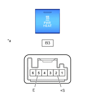
a.
E467049C01
1.521,1.438 1.927,1.677 0.406,0.24 2.208,3.146 2.073,2.719 true 1.26,3.146 1.365,2.719 true 1.625,1.469 1.938,1.625 0.313,0.156 10 false I93 2.177,3.188 2.573,3.427 0.396,0.24 10 false +S 0.271,1.385 0.521,1.583 0.25,0.198 10 false *a 1.177,3.177 1.573,3.417 0.396,0.24 10 false E
*a Component without harness connected
(Heater Switch Assembly)


Measure the resistance according to the value(s) in the table below.

Standard Resistance:
Tester Connection Switch Condition Specified Condition

Click Location & Routing(I93)Location & Routing

Click Connector(I93)Instrument Panel>Instrument Panel Wire / Mobile Wireless Charger Cord / No. 1 Navigation Wire / No. 2 Instrument Panel Wire / No. 5 Instrument Panel Wire / Telephone Computer Wire>Heater Switch Assembly

I93-2 (+S) - I93-5 (E) Pushed (ON) Below 1 Ω
I93-2 (+S) - I93-5 (E) Not pushed (OFF) 10 kΩ or higher


If the result is not as specified, replace the heater switch assembly.
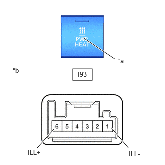

b.
E467049C02
1.521,1.438 1.927,1.677 0.406,0.24 2.677,3.083 2.323,2.667 true 0.781,3.083 1.125,2.698 true 2.406,1.24 1.74,0.792 true 0.583,3.094 0.958,3.344 0.375,0.25 10 false ILL+ 2.688,3.125 3.083,3.365 0.396,0.24 10 false ILL- 1.625,1.469 1.938,1.625 0.313,0.156 10 false I93 2.458,1.188 2.719,1.427 0.26,0.24 10 false *a 0.271,1.385 0.521,1.583 0.25,0.198 10 false *b
*a Illumination
*b Component without harness connected
(Heater Switch Assembly)


Check the illumination.

i.

Apply battery voltage to the connector and check the illumination conditions.

OK:
Tester Connection Specified Condition

Click Location & Routing(I93)Location & Routing

Click Connector(I93)Instrument Panel>Instrument Panel Wire / Mobile Wireless Charger Cord / No. 1 Navigation Wire / No. 2 Instrument Panel Wire / No. 5 Instrument Panel Wire / Telephone Computer Wire>Heater Switch Assembly

Battery positive (+) → I93-6 (ILL+)
Battery negative (-) → I93-1 (ILL-)
Illumination illuminates


If the result is not as specified, replace the heater switch assembly.
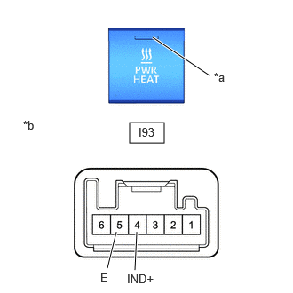


c.
E467049C03
1.521,1.438 1.927,1.677 0.406,0.24 2.458,0.885 1.792,0.438 true 1.26,3.146 1.365,2.719 true 1.583,3.167 1.604,2.719 true 1.625,1.469 1.938,1.625 0.313,0.156 10 false I93 2.51,0.823 2.771,1.063 0.26,0.24 10 false *a 0.271,1.385 0.521,1.583 0.25,0.198 10 false *b 1.177,3.177 1.573,3.417 0.396,0.24 10 false E 1.49,3.188 2.01,3.427 0.521,0.24 10 false IND+
*a Indicator
*b Component without harness connected
(Heater Switch Assembly)


Check the indicator.

i.

Apply battery voltage to the connector and check the indicator conditions.

OK:
Tester Connection Condition Specified Condition

Click Location & Routing(I93)Location & Routing

Click Connector(I93)Instrument Panel>Instrument Panel Wire / Mobile Wireless Charger Cord / No. 1 Navigation Wire / No. 2 Instrument Panel Wire / No. 5 Instrument Panel Wire / Telephone Computer Wire>Heater Switch Assembly

Battery positive (+) → I93-4(IND+)
Battery negative (-) → I93-5(E)
Switch pushed (ON) Indicator illuminates


If the result is not as specified, replace the heater switch assembly.


Hide 84453 2.INSPECT IDLE UP SWITCH (w/o Viscous Heater)
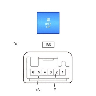
a.
E470123C01
1.521,1.5 1.938,1.698 0.417,0.198 1.313,3.125 1.396,2.667 true 1.948,3.104 1.99,2.646 true 0.49,1.479 0.802,1.677 0.313,0.198 10 false *a 1.635,1.521 1.948,1.719 0.313,0.198 10 false I86 1.26,3.135 1.656,3.354 0.396,0.219 10 false +S 1.917,3.135 2.313,3.354 0.396,0.219 10 false E
*a Component without harness connected
(Idle Up Switch)


Measure the resistance according to the value(s) in the table below.

Standard Resistance:
Tester Connection Switch Condition Specified Condition

Click Location & Routing(I86)Location & Routing

Click Connector(I86)Instrument Panel>Instrument Panel Wire / Mobile Wireless Charger Cord / No. 1 Navigation Wire / No. 2 Instrument Panel Wire / No. 5 Instrument Panel Wire / Telephone Computer Wire>Idle Up Switch

I86-2 (E) - I86-5 (+S) Pushed (ON) Below 1 Ω
I86-2 (E) - I86-5 (+S) Not pushed (OFF) 10 kΩ or higher


If the result is not as specified, replace the idle up switch.
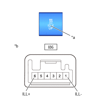

b.
E470123C02
1.521,1.5 1.938,1.698 0.417,0.198 2.385,1.208 1.719,0.875 true 2.635,3.104 2.302,2.635 true 0.885,3.094 1.156,2.646 true 0.49,1.479 0.802,1.677 0.313,0.198 10 false *b 2.427,1.188 2.74,1.385 0.313,0.198 10 false *a 1.635,1.521 1.948,1.719 0.313,0.198 10 false I86 0.76,3.115 1.156,3.333 0.396,0.219 10 false ILL+ 2.552,3.115 2.948,3.333 0.396,0.219 10 false ILL-
*a Illumination
*b Component without harness connected
(Idle Up Switch)


Check the illumination.

i.

Apply battery voltage to the connector terminal and check the illumination.

OK:
Tester Connection Specified Condition

Click Location & Routing(I86)Location & Routing

Click Connector(I86)Instrument Panel>Instrument Panel Wire / Mobile Wireless Charger Cord / No. 1 Navigation Wire / No. 2 Instrument Panel Wire / No. 5 Instrument Panel Wire / Telephone Computer Wire>Idle Up Switch

Battery positive (+) → I86-6 (ILL+)
Battery negative (-) → I86-1 (ILL-)
Illumination illuminates


If the result is not as specified, replace the idle up switch.