Home › Engine / Hybrid System › F33A-FTV (INTAKE / EXHAUST) › VACUUM SWITCHING VALVE › from 2021.07
RM38G0E _51 Engine / Hybrid System _106333 F33A-FTV INTAKE / EXHAUST _0497592 VACUUM SWITCHING VALVE G

F33A-FTV INTAKE / EXHAUST  VACUUM SWITCHING VALVE  INSPECTION  


PROCEDURE

Hide 25860 1.INSPECT NO. 1 VACUUM SWITCHING VALVE ASSEMBLY (for ECV)

a.

Inspect the resistance.

i.
A491489C02
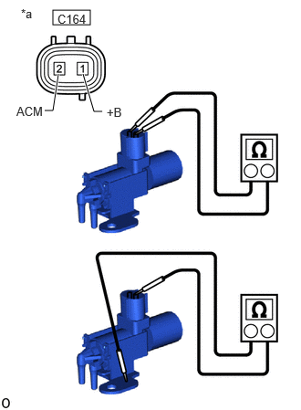
0.604,0.115 1.031,0.281 0.427,0.167 0.948,0.844 1.073,1.271 1.073,1.271 1.167,1.271 true 0.51,1.26 0.604,1.26 0.604,1.26 0.667,0.844 true 0.24,0.073 0.49,0.24 0.25,0.167 10 false *a 0.188,1.188 0.542,1.375 0.354,0.188 10 false ACM 1.219,1.198 1.479,1.406 0.26,0.208 10 false +B 0.656,0.135 1.083,0.302 0.427,0.167 10 false C164
*a Component without harness connected
(No. 1 Vacuum Switching Valve Assembly)


Measure the resistance according to the value(s) in the table below.

Standard Resistance:
Tester Connection Condition Specified Condition

Click Location & Routing(C164)Location & Routing

Click Connector(C164)Engine Compartment>Connecting Wire / Cooling Fan Wire / Engine Wire / Fuel Pump Motor Wire / No. 1 Connecting Wire / No. 10 Engine Wire / No. 2 Connecting Wire / No. 3 Connecting Wire / No. 4 Connecting Wire / Sensor Wire / Turbocharger Wire>Duty Vacuum Switching Valve

C164-1 (+B) - C164-2 (ACM) 20°C (68°F) 37 to 44 Ω
C164-1 (+B) - Body ground 20°C (68°F) 1 MΩ or higher
C164-2 (ACM) - Body ground 20°C (68°F) 1 MΩ or higher


ii.

If the result is not as specified, replace the No. 1 vacuum switching valve assembly.


b.

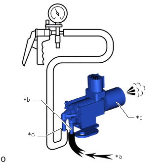
Check the operation of the No. 1 vacuum switching valve assembly.

i.
A491491C01
2.458,2.146 2.708,2.479 2.708,2.479 2.813,2.479 true 0.698,2.104 0.865,2.104 0.865,2.104 1.5,2.729 true 0.792,2.865 0.958,2.865 0.958,2.865 1.292,2.698 true 2.438,3.229 2.75,3.427 0.313,0.198 10 false *a 0.5,2.031 0.75,2.177 0.25,0.146 10 false *b 0.594,2.76 0.844,2.906 0.25,0.146 10 false *c 2.875,2.406 3.125,2.552 0.25,0.146 10 false *d
*a Air
*b Port E
*c Port F
*d Filter


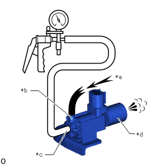
When a vacuum of 60 kPa (450 mmHg, 18 in.Hg) is applied to port F, check that air flows from port E to the filter.

ii.
A491493C01
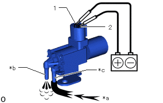
0.948,1.583 0.552,1.427 0.552,1.427 0.385,1.427 true 2.031,1.479 1.833,1.479 1.833,1.479 1.146,1.646 true 1.688,0.563 2.208,0.563 true 1.24,0.156 1.396,0.156 1.396,0.156 1.583,0.49 true 2.167,2.01 2.417,2.177 0.25,0.167 10 false *a 0.198,1.375 0.375,1.531 0.177,0.156 10 false *b 2.073,1.417 2.302,1.583 0.229,0.167 10 false *c 2.292,0.51 2.438,0.688 0.146,0.177 10 false 2 1.125,0.104 1.271,0.281 0.146,0.177 10 false 1
*a Air
*b Port F
*c Port E


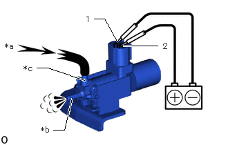
Apply battery voltage 12 V across terminals 1 and 2.


iii.

Check that air flows from port E to port F.


iv.

If the result is not as specified, replace the No. 1 vacuum switching valve assembly.


Hide 25860D 2.INSPECT NO. 2 VACUUM SWITCHING VALVE ASSEMBLY (for ACV)

a.

Inspect the resistance.

i.
A491488C01
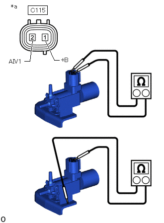
0.583,0.115 0.99,0.302 0.406,0.188 0.51,1.281 0.625,1.281 0.625,1.281 0.677,0.865 true 0.948,0.854 1.135,1.26 1.135,1.26 1.24,1.26 true 0.188,1.219 0.531,1.438 0.344,0.219 10 false AIV1 1.281,1.188 1.583,1.406 0.302,0.219 10 false +B 0.229,0.063 0.458,0.292 0.229,0.229 10 false *a 0.646,0.146 1.021,0.344 0.375,0.198 10 false C115
*a Component without harness connected
(No. 2 Vacuum Switching Valve Assembly)


Measure the resistance according to the value(s) in the table below.

Standard Resistance:
Tester Connection Condition Specified Condition

Click Location & Routing(C115)Location & Routing

Click Connector(C115)Engine Compartment>Connecting Wire / Cooling Fan Wire / Engine Wire / Fuel Pump Motor Wire / No. 1 Connecting Wire / No. 10 Engine Wire / No. 2 Connecting Wire / No. 3 Connecting Wire / No. 4 Connecting Wire / Sensor Wire / Turbocharger Wire>Intake Air Control Valve Assembly

C115-1 (+B) - C115-2 (AIV1) 20°C (68°F) 37 to 44 Ω
C115-1 (+B) - Body ground 20°C (68°F) 1 MΩ or higher
C115-2 (AIV1) - Body ground 20°C (68°F) 1 MΩ or higher


ii.

If the result is not as specified, replace the No. 2 vacuum switching valve assembly.


b.

Check the operation of the No. 2 vacuum switching valve assembly.

i.
A491490C01
2.448,2.448 2.698,2.781 2.698,2.781 2.802,2.781 true 0.635,1.885 0.802,1.885 0.802,1.885 1.479,2.438 true 0.938,3.219 1.104,3.219 1.104,3.219 1.385,2.719 true 2.406,1.531 2.719,1.729 0.313,0.198 10 false *a 0.438,1.813 0.688,1.958 0.25,0.146 10 false *b 0.75,3.146 1,3.292 0.25,0.146 10 false *c 2.844,2.729 3.094,2.875 0.25,0.146 10 false *d
*a Air
*b Port E
*c Port F
*d Filter


When a vacuum of 60 kPa (450 mmHg, 18 in.Hg) is applied to port F, check that air flows from port E to the filter.

ii.
A491492C01
1.271,1.208 0.719,1.021 0.719,1.021 0.552,1.021 true 1.083,1.479 0.969,1.958 0.969,1.958 0.802,1.958 true 1.854,0.688 2.375,0.688 true 1.417,0.281 1.573,0.281 1.573,0.281 1.76,0.615 true 0.073,0.625 0.323,0.792 0.25,0.167 10 false *a 0.615,1.885 0.792,2.042 0.177,0.156 10 false *b 0.354,0.958 0.573,1.125 0.219,0.167 10 false *c 2.458,0.625 2.604,0.802 0.146,0.177 10 false 2 1.292,0.219 1.438,0.396 0.146,0.177 10 false 1
*a Air
*b Port F
*c Port E


Apply battery voltage 12 V across terminals 1 and 2.


iii.

Check that air flows from port E to port F.


iv.

If the result is not as specified, replace the No. 2 vacuum switching valve assembly.