TELEMATICS TELEMATICS SYSTEM(w/o Emergency Call Service) SYSTEM DESCRIPTION
TELEMATICS SYSTEM OUTLINE
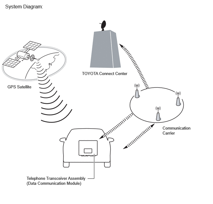
The telematics system is a telematics service that links the vehicle and service center network (provides information from the service center or content providers).
In order for the user to use the service center service, it is necessary to create a contract at the dealer and register the vehicle and user information.
SYSTEM FUNCTION
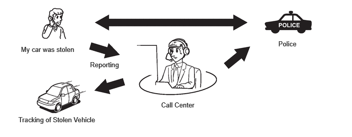
Stolen Vehicle Locator
After the vehicle has been reported stolen to the police, the customer can contact the call center to begin the stolen vehicle locator process. The operator locates this vehicle by GPS and provides information to the police.
FUNCTION OF MAIN COMPONENTS
| Component | Function | ||
|---|---|---|---|
| Map Light Assembly
·
LED Indicator Light |
Green |
·
Illuminates for 2 seconds after the ignition switch is turned to ON and the LED indicator light indicator (red) has illuminated for 2 seconds.
·
Turns on when the system is operating normally. |
|
| Red |
·
Illuminates when the mobilephone battery needs to be replaced.
·
Illuminates in diagnostic mode to indicate a DTC.
·
Illuminates in diagnostic mode to indicate a specific vehicle history (RoB). |
||
| Navigation Antenna Assembly | Telephone Antenna (Sub) | Receives signals from the service center. (Connect as sub) | |
| Roof Antenna Assembly | Telephone Antenna (Main) | Sends and receives the data and voice signals used for the service center through a communication network. (Connect as main) | |
| GNSS Antenna | Receives GNSS radio signals and sends them to the telephone transceiver assembly. | ||
| Telephone Transceiver Assembly |
·
Uses the roof antenna assembly to send and receive data used for the service center via a communication network.
-
Sends vehicle information signals to the service center.
-
Receives remote operation signals from the service center.
-
When a warning occurs, the telephone transceiver assembly receives a warning ON signal from the combination meter assembly via CAN communication and sends it to the service center. |
||
| Mobilephone Battery | The mobilephone battery conducts a self-diagnosis every time the ignition switch is turned to ON. | ||
| Certification ECU (Smart Key ECU Assembly) | Receives the remote engine start and stop signal from the user's smartphone or electrical key transmitter sub-assembly via the telephone transceiver assembly and initiates the engine start operation. | ||
MAYDAY ID OUTLINE
The telematics transceiver has serial numbers (IMEI, ICCID) which can be used to identify the individual device when servicing.
The IMEI and ICCID are printed on the label attached to the telephone transceiver assembly.
COMMUNICATION SYSTEM
CAN Communication Outline
The telematics system uses CAN communication between the telephone transceiver assembly and ECUs.
DIAGNOSTIC FUNCTION OUTLINE
The telematics system has a diagnostic function (the result will be displayed on the GTS).