BODY WELD POINT FIT STANDARD / ADJUSTMENT METHOD ADJUSTMENT
INSPECT HOOD SUB-ASSEMBLY
Check that the clearance measurements of areas A to D are within the standard range.
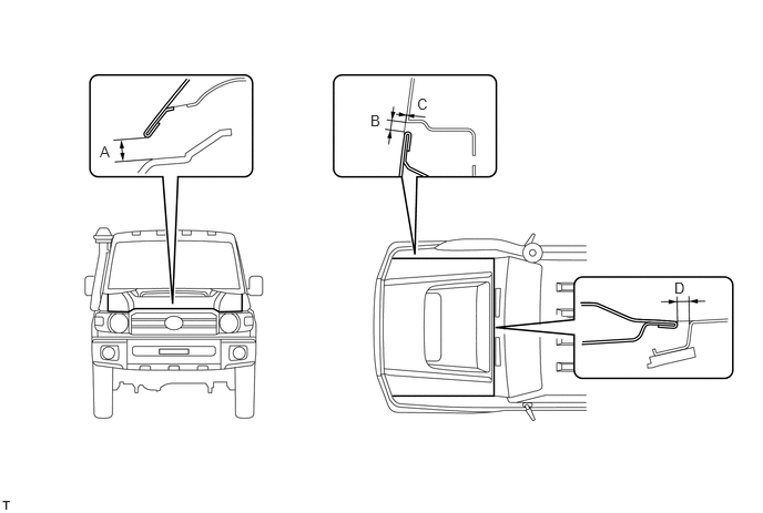
- Standard Clearance:
-
Area Specified Condition Area Specified Condition A 9.35 to 12.35 mm (0.3681 to 0.4862 in.) B 3.4 to 6.4 mm (0.1339 to 0.2520 in.) C -1.5 to 1.5 mm (-0.0591 to 0.0591 in.) D 3.5 to 6.5 mm (0.1378 to 0.2559 in.)
ADJUST HOOD SUB-ASSEMBLY
Adjust the hood's position.
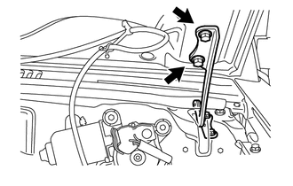
Loosen the hood's hinge bolts and adjust the hood's position.
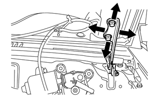
Move the hood and adjust the clearance between the hood and front fender.
Tighten the 4 hood's hinge bolts after the adjustment.
- Torque:
- 18 N*m (184 kgf*cm, 13 ft.*lbf)
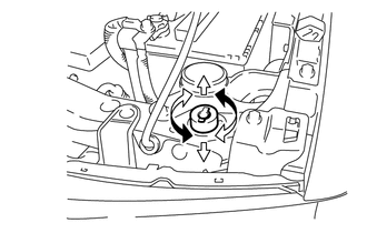
Adjust the cushion rubber so that the height of the hood and fender are aligned.
- HINT:
-
Raise or lower the hood's front end by turning the cushion rubber.
Adjust the hood lock.
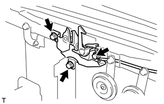
Loosen the 3 bolts.
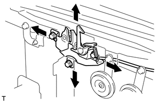
Adjust the hood lock position so that the striker can enter it smoothly.
Tighten the 3 bolts after the adjustment.
- Torque:
- 7.8 N*m (80 kgf*cm, 69 in.*lbf)
INSPECT FRONT DOOR PANEL SUB-ASSEMBLY (for Model Code #J71 Series)
Check that the clearance measurements of areas A to G are within the standard range.
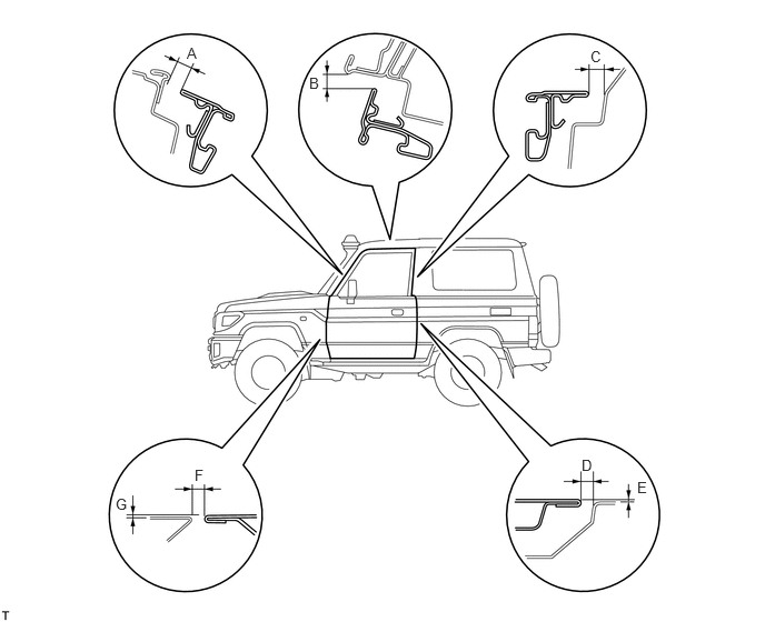
- Standard Clearance:
-
Area Specified Condition Area Specified Condition A 5.0 to 9.0 mm (0.197 to 0.354 in.) B 6.0 to 10.0 mm (0.236 to 0.394 in.) C 5.0 to 9.0 mm (0.197 to 0.354 in.) D 3.5 to 7.5 mm (0.138 to 0.295 in.) E -1.5 to 1.5 mm (-0.0591 to 0.0591 in.) F 3.5 to 7.5 mm (0.1378 to 0.295 in.) G -1.5 to 1.5 mm (-0.0591 to 0.0591 in.) - -
INSPECT FRONT DOOR PANEL SUB-ASSEMBLY (for Model Code #J76 Series)
Check that the clearance measurements of areas A to G are within the standard range.
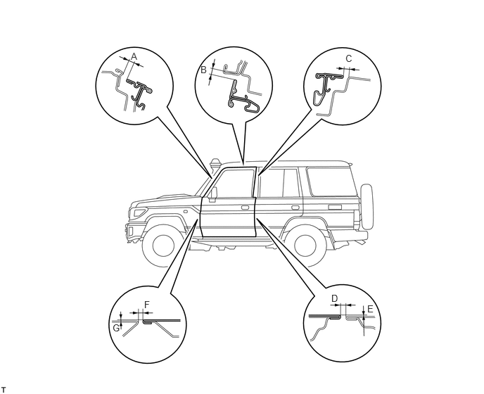
- Standard Clearance:
-
Area Specified Condition Area Specified Condition A 5.0 to 9.0 mm (0.197 to 0.354 in.) B 4.5 to 8.5 mm (0.177 to 0.335 in.) C 5.2 to 9.2 mm (0.205 to 0.362 in.) D 4.2 to 7.2 mm (0.165 to 0.283 in.) E -1.5 to 1.5 mm (-0.0591 to 0.0591 in.) F 3.7 to 7.7mm (0.146 to 0.303 in.) G -1.5 to 1.5 mm (-0.0591 to 0.0591 in.) - -
INSPECT FRONT DOOR PANEL SUB-ASSEMBLY (for Model Code #J79 Series, for Single Cab)
Check that the clearance measurements of areas A to G are within the standard range.
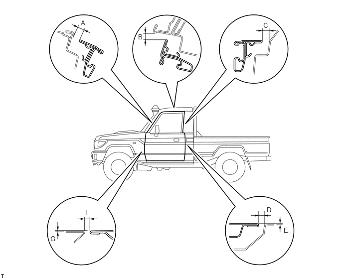
- Standard Clearance:
-
Area Specified Condition Area Specified Condition A 5.0 to 9.0 mm (0.197 to 0.354 in.) B 6.0 to 10.0 mm (0.236 to 0.394 in.) C 5.0 to 9.0 mm (0.197 to 0.354 in.) D 3.5 to 7.5 mm (0.138 to 0.295 in.) E -1.5 to 1.5 mm (-0.0591 to 0.0591 in.) F 3.5 to 7.5 mm (0.1378 to 0.295 in.) G -1.5 to 1.5 mm (-0.0591 to 0.0591 in.) - -
INSPECT FRONT DOOR PANEL SUB-ASSEMBLY (for Model Code #J79 Series, for Double Cab)
Check that the clearance measurements of areas A to G are within the standard range.
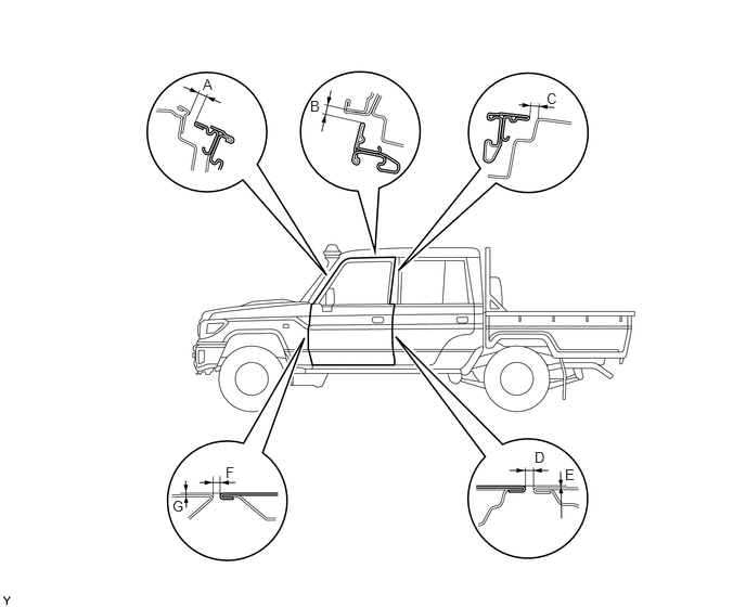
- Standard Clearance:
-
Area Specified Condition Area Specified Condition A 5.0 to 9.0 mm (0.197 to 0.354 in.) B 4.5 to 8.5 mm (0.177 to 0.335 in.) C 5.2 to 9.2 mm (0.205 to 0.362 in.) D 4.2 to 8.2 mm (0.165 to 0.283 in.) E -1.5 to 1.5 mm (-0.0591 to 0.0591 in.) F 3.7 to 7.7 mm (0.146 to 0.303 in.) G -1.5 to 1.5 mm (-0.0591 to 0.0591 in.) - -
INSPECT FRONT DOOR PANEL SUB-ASSEMBLY (for Model Code #J78 Series)
Check that the clearance measurements of areas A to G are within the standard range.
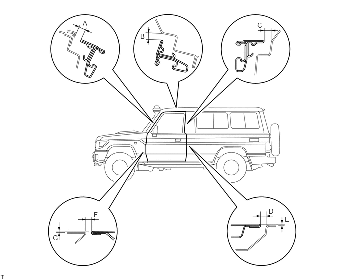
- Standard Clearance:
-
Area Specified Condition Area Specified Condition A 5.0 to 9.0 mm (0.197 to 0.354 in.) B 6.0 to 10.0 mm (0.236 to 0.394 in.) C 5.0 to 9.0 mm (0.197 to 0.354 in.) D 3.5 to 7.5 mm (0.138 to 0.295 in.) E -1.5 to 1.5 mm (-0.0591 to 0.0591 in.) F 3.5 to 7.5 mm (0.138 to 0.295 in.) G -1.5 to 1.5 mm (-0.0591 to 0.0591 in.) - -
INSPECT FRONT DOOR PANEL SUB-ASSEMBLY (for Canvas Top)
Check that the clearance measurements of areas A to G are within the standard range.
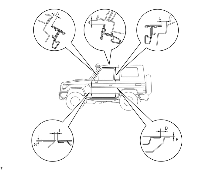
- Standard Clearance:
-
Area Specified Condition Area Specified Condition A 5.0 to 9.0 mm (0.197 to 0.354 in.) B 6.0 to 10.0 mm (0.236 to 0.394 in.) C 5.0 to 9.0 mm (0.197 to 0.354 in.) D 3.5 to 7.5 mm (0.138 to 0.295 in.) E -1.5 to 1.5 mm (-0.0591 to 0.0591 in.) F 3.5 to 7.5 mm (0.138 to 0.295 in.) G -1.5 to 1.5 mm (-0.0591 to 0.0591 in.) - -
ADJUST FRONT DOOR PANEL SUB-ASSEMBLY LH
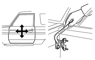
Using a SST, loosen the body's hinge bolts and adjust the door's position.
- SST
-
09812-00010
Tighten the body's hinge bolts after the adjustment.
- Torque:
- 24 N*m (245 kgf*cm, 18 ft.*lbf)
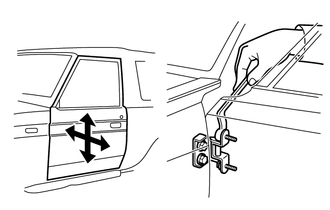
Loosen the door's hinge bolts and adjust the door's position.
Tighten the body's hinge bolts after the adjustment.
- Torque:
- 24 N*m (245 kgf*cm, 18 ft.*lbf)
ADJUST DOOR LOCK STRIKER
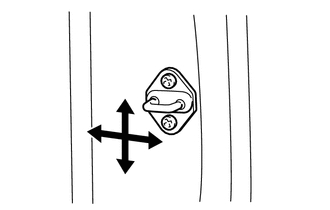
Using a T40 "TORX" socket wrench, adjust the striker position by slightly loosening the striker mounting screws and hitting the striker with a brass bar and hammer.
- Torque:
- 12 N*m (122 kgf*cm, 9 ft.*lbf)
INSPECT REAR DOOR PANEL SUB-ASSEMBLY (for Model Code #J76 Series)
Check that the clearance measurements of areas A to G are within the standard range.
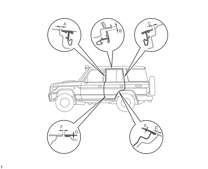
- Standard Clearance:
-
Area Specified Condition Area Specified Condition A 5.2 to 9.2 mm (0.205 to 0.362 in.) B 4.5 to 8.5 mm (0.177 to 0.335 in.) C 4.3 to 8.3 mm (0.169 to 0.327 in.) D 3.7 to 7.7 mm (0.146 to 0.303 in.) E -1.5 to 1.5 mm (-0.0591 to 0.0591 in.) F 4.2 to 7.2 mm (0.165 to 0.283 in.) G -1.5 to 1.5 mm (-0.0591 to 0.0591 in.) - -
INSPECT REAR DOOR PANEL SUB-ASSEMBLY (for Model Code #J79 Series)
Check that the clearance measurements of areas A to G are within the standard range.
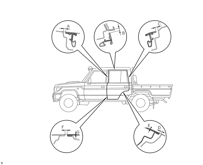
- Standard Clearance:
-
Area Specified Condition Area Specified Condition A 5.2 to 9.2 mm (0.205 to 0.362 in.) B 4.5 to 8.5 mm (0.177 to 0.335 in.) C 4.3 to 8.3 mm (0.169 to 0.327 in.) D 3.7 to 7.7 mm (0.146 to 0.303 in.) E -1.5 to 1.5 mm (-0.0591 to 0.0591 in.) F 4.2 to 7.2 mm (0.165 to 0.283 in.) G -1.5 to 1.5 mm (-0.0591 to 0.0591 in.) - -
ADJUST REAR DOOR PANEL SUB-ASSEMBLY LH
Remove the front door scuff plate.
Remove the rear door scuff plate.
Remove the lower center pillar garnish.
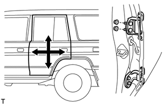
Loosen the body's hinge bolts and nuts adjust the door's position.
Tighten the body's hinge bolts and nuts after the adjustment.
- Torque:
- 24 N*m (245 kgf*cm, 18 ft.*lbf)
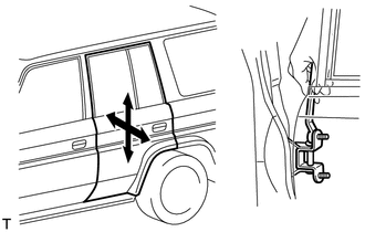
Loosen the door's hinge bolts and adjust the door's position.
Tighten the body's hinge bolts after the adjustment.
- Torque:
- 24 N*m (245 kgf*cm, 18 ft.*lbf)
ADJUST DOOR LOCK STRIKER
Using a T40 "TORX" socket wrench, adjust the striker position by slightly loosening the striker mounting screws and hitting the striker with a brass bar and hammer.
- Torque:
- 12 N*m (122 kgf*cm, 9 ft.*lbf)
INSPECT BACK DOOR PANEL SUB-ASSEMBLY LH
Check that the clearance measurements of areas A to G are within the standard range.
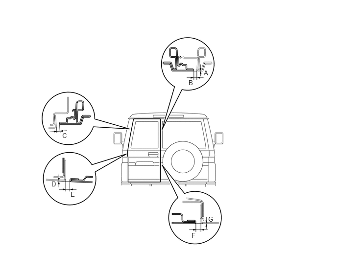
- Standard Clearance:
-
Area Specified Condition Area Specified Condition A -1.5 to 1.5 mm (-0.0591 to 0.0591 in.) B 5.0 to 9.0 mm (0.197 to 0.354 in.) C 5.0 to 9.0 mm (0.197 to 0.354 in.) D -1.5 to 1.5 mm (-0.0591 to 0.0591 in.) E -4.8 to 7.8 mm (0.189 to 0.307 in.) F 4.5 to 7.5 mm (0.177 to 0.295 in.) G -1.5 to 1.5 mm (-0.0591 to 0.0591 in.) - -
ADJUST BACK DOOR PANEL SUB-ASSEMBLY LH
Remove the hole plug.
Remove the rear speaker cover.
Remove the rear speaker grille.
Remove the rear speaker assembly.
Remove the speaker box.
Remove the back door inside handle assembly.
Remove the back door trim panel assembly LH.
Remove the back door service hole cover LH.
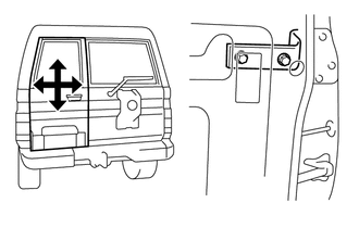
Loosen the body's hinge bolts and adjust the door's position.
Tighten the body's hinge bolts after the adjustment.
- Torque:
- 37 N*m (377 kgf*cm, 27 ft.*lbf)
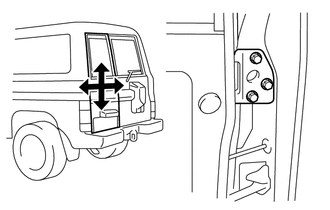
Loosen the door's hinge bolts and adjust the door's position.
Tighten the body's hinge bolts after the adjustment.
- Torque:
- 18 N*m (184 kgf*cm, 13 ft.*lbf)
ADJUST BACK DOOR LOCK STRIKER PLATE ASSEMBLY
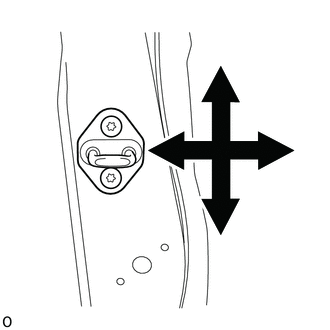
Using a T40 "TORX" socket wrench, adjust the striker position by slightly loosening the striker mounting screws and hitting the striker with a brass bar and hammer.
- Torque:
- 12 N*m (122 kgf*cm, 9 ft.*lbf)
ADJUST BACK DOOR PANEL SUB-ASSEMBLY RH
Check that the clearance measurements of areas A to E are within the standard range.
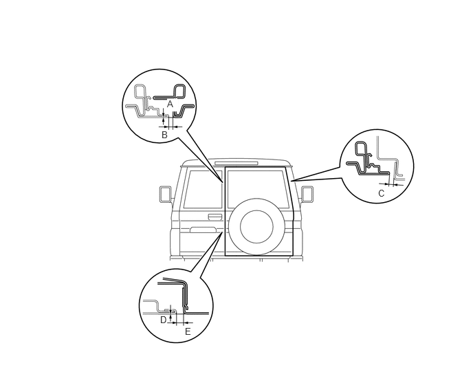
- Standard Clearance:
-
Area Specified Condition Area Specified Condition A -1.5 to 1.5 mm (-0.0591 to 0.0591 in.) B 5.5 to 8.5 mm (0.217 to 0.335 in.) C 5.5 to 8.5 mm (0.217 to 0.335 in.) D -1.5 to 1.5 mm (-0.0591 to 0.0591 in.) E 4.5 to 7.5 mm (0.177 to 0.295 in.) - -
ADJUST BACK DOOR PANEL SUB-ASSEMBLY RH
Remove the hole plug.
Remove the rear speaker grille.
Remove the rear speaker cover.
Remove the rear speaker assembly.
Remove the speaker box.
Remove the back door trim panel assembly RH.
Remove the back door service hole cover RH.
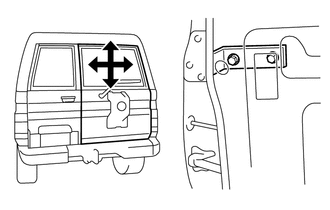
Loosen the body's hinge bolts and adjust the door's position.
Tighten the body's hinge bolts after the adjustment.
- Torque:
- 37 N*m (377 kgf*cm, 27 ft.*lbf)
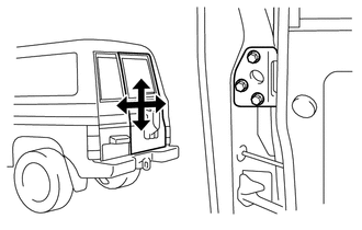
Loosen the door's hinge bolts and adjust the door's position.
Tighten the body's hinge bolts after the adjustment.
- Torque:
- 18 N*m (184 kgf*cm, 13 ft.*lbf)
ADJUST BACK DOOR UPPER LOCK STRIKER ASSEMBLY
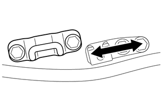
Check that the fit and door lock linkages are adjusted correctly.
Adjust the striker position by slightly loosening the striker mounting bolts or screws, and hitting the striker with a brass bar and hammer.
Tighten the striker mounting bolts or screws again.
ADJUST BACK DOOR LOCK STRIKER ASSEMBLY
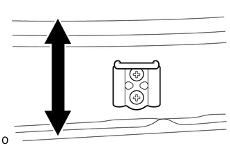
Check that the fit and door lock linkages are adjusted correctly.
Adjust the striker position by slightly loosening the striker mounting bolts or screws, and hitting the striker with a brass bar and hammer.
Tighten the striker mounting bolts or screws again.