BODY DIMENSIONS FRAME TWO-DIMENSIONAL DISTANCE
for Double Cab
Upper Face
- HINT:
-
·
Length measurements are indicated at the points where the arrows extending from the zero point intersect the lines that extend towards the outside of the illustration from each point.
·In cases in which only one dimension is given, left and right are symmetrical.
·For symbols, capital letters indicate right side of vehicle, small letters indicate left side of vehicle (seen from rear).
| Symbol | Name | Hole Diameter mm (in.) |
|---|---|---|
| A, a | Front Bumper Side Mounting Bracket Installation Hole | φ14 (0.55) |
| B, b | Body Mounting Hole | φ24 (0.94) |
| C, c | Shock Absorber Installation Hole | φ24 (0.94) |
| D, d | Body Mounting Hole | φ24 (0.94) |
| E, e | Body Mounting Hole | φ24 (0.94) |
| F, f | Body Mounting Hole | φ24 (0.94) |
| G, g | Rear Body Mounting Hole | φ15 (0.59) |
| H, h | Rear Body Mounting Hole | φ11 (0.43) |
| J, j | Rear Body Mounting Hole | φ15 (0.59) |
| Wheel Base | 3180 mm (125.20 in.) |
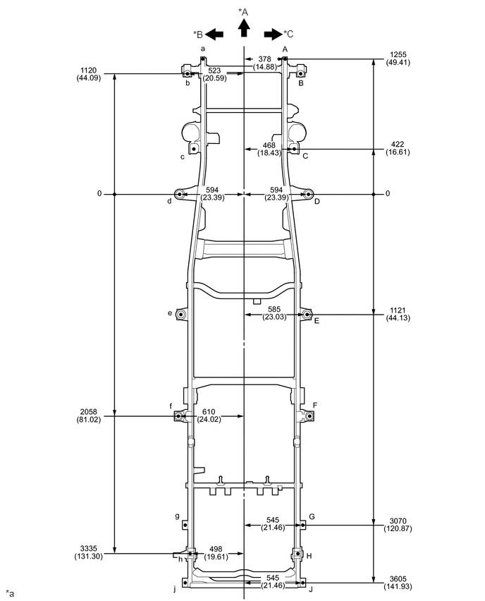
| *A | FRONT | *B | LH |
| *C | RH | - | - |
| *a | mm (in.) |
- | - |
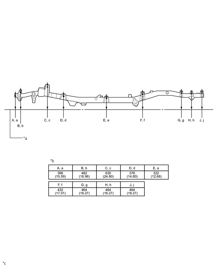
| *a | Imaginary Datum Line | *b | Height from Imaginary Datum Line |
| *c | mm (in.) |
- | - |
Lower Face
- HINT:
-
·
Length measurements are indicated at the points where the arrows extending from the zero point intersect the lines that extend towards the outside of the illustration from each point.
·In cases in which only one dimension is given, left and right are symmetrical.
·For symbols, capital letters indicate right side of vehicle, small letters indicate left side of vehicle (seen from rear).
| Symbol | Name | Hole Diameter mm (in.) |
|---|---|---|
| A, a | Front Bumper Side Mounting Bracket Installation Hole | φ13 (0.51) |
| B | Lateral Control Rod Installation Hole | φ16.5 (0.65) |
| C, c | Front Stabilizer Bracket Installation Nut | M8 (0.31) |
| D, d | Leading Arm Installation Hole | φ18.5 (0.73) |
| E, e | Rear Spring Bracket Pin Installation Hole | φ14 (0.55) |
| F, f | Rear Spring Bumper Installation Nut | M8 (0.31) |
| G, g | Spring Shackle Installation Hole | φ40 (1.57) |
| Wheel Base | 3180 mm (125.20 in.) |
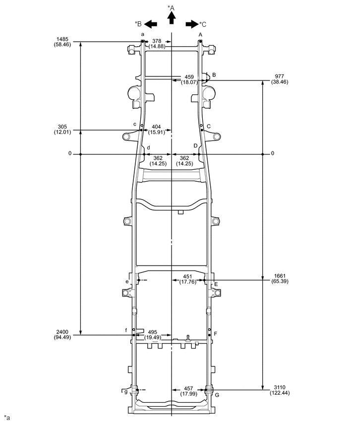
| *A | FRONT | *B | LH |
| *C | RH | - | - |
| *a | mm (in.) |
- | - |
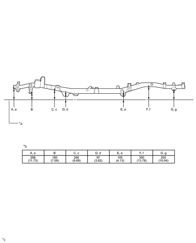
| *a | Imaginary Datum Line | *b | Height from Imaginary Datum Line |
| *c | mm (in.) |
- | - |
for Regular Cab
Upper Face
- HINT:
-
·
Length measurements are indicated at the points where the arrows extending from the zero point intersect the lines that extend towards the outside of the illustration from each point.
·In cases in which only one dimension is given, left and right are symmetrical.
·For symbols, capital letters indicate right side of vehicle, small letters indicate left side of vehicle (seen from rear).
| Symbol | Name | Hole Diameter mm (in.) |
|---|---|---|
| A, a | Front Bumper Side Mounting Bracket Installation Hole | φ14 (0.55) |
| B, b | Body Mounting Hole | φ24 (0.94) |
| C, c | Shock Absorber Installation Hole | φ24 (0.94) |
| D, d | Body Mounting Hole | φ24 (0.94) |
| E, e | Body Mounting Hole | φ24 (0.94) |
| F, f | Rear Body Mounting Hole | φ15 (0.59) |
| G, g | Rear Body Mounting Hole | φ15 (0.59) |
| H, h | Rear Body Mounting Hole | φ15 (0.59) |
| J, j | Rear Body Mounting Hole | φ11 (0.43) |
| K, k | Rear Body Mounting Hole | φ15 (0.59) |
| Wheel Base | 3180 mm (125.20 in.) |
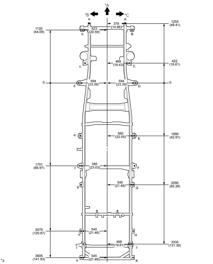
| *A | FRONT | *B | LH |
| *C | RH | - | - |
| *a | mm (in.) |
- | - |
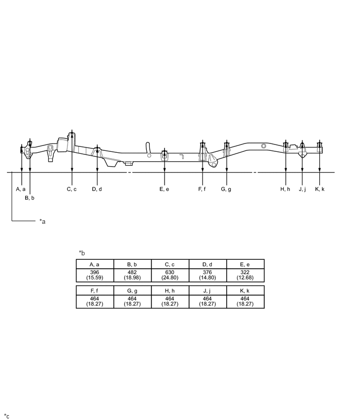
| *a | Imaginary Datum Line | *b | Height from Imaginary Datum Line |
| *c | mm (in.) |
- | - |
Lower Face
- HINT:
-
·
Length measurements are indicated at the points where the arrows extending from the zero point intersect the lines that extend towards the outside of the illustration from each point.
·In cases in which only one dimension is given, left and right are symmetrical.
·For symbols, capital letters indicate right side of vehicle, small letters indicate left side of vehicle (seen from rear).
| Symbol | Name | Hole Diameter mm (in.) |
|---|---|---|
| A, a | Front Bumper Side Mounting Bracket Installation Hole | φ13 (0.51) |
| B | Lateral Control Rod Installation Hole | φ16.5 (0.65) |
| C, c | Front Stabilizer Bracket Installation Nut | M8 (0.31) |
| D, d | Leading Arm Installation Hole | φ18.5 (0.73) |
| E, e | Rear Spring Bracket Pin Installation Hole | φ14 (0.55) |
| F, f | Rear Spring Bumper Installation Nut | M8 (0.31) |
| G, g | Spring Shackle Installation Hole | φ40 (1.57) |
| Wheel Base | 3180 mm (125.20 in.) |
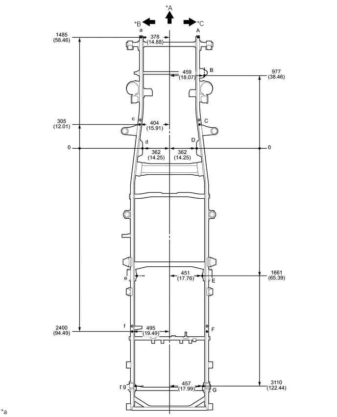
| *A | FRONT | *B | LH |
| *C | RH | - | - |
| *a | mm (in.) |
- | - |
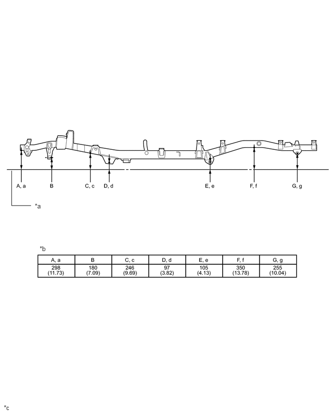
| *a | Imaginary Datum Line | *b | Height from Imaginary Datum Line |
| *c | mm (in.) |
- | - |
for Regular Cab (for Australia (2016/08-))
Upper Face
- HINT:
-
·
Length measurements are indicated at the points where the arrows extending from the zero point intersect the lines that extend towards the outside of the illustration from each point.
·In cases in which only one dimension is given, left and right are symmetrical.
·For symbols, capital letters indicate right side of vehicle, small letters indicate left side of vehicle (seen from rear).
| Symbol | Name | Hole Diameter mm (in.) |
|---|---|---|
| A, a | Front Bumper Side Mounting Bracket Installation Hole | φ14 (0.55) |
| B, b | Body Mounting Hole | φ24 (0.94) |
| C, c | Shock Absorber Installation Hole | φ24 (0.94) |
| D, d | Body Mounting Hole | φ24 (0.94) |
| E, e | Body Mounting Hole | φ24 (0.94) |
| F, f | Rear Body Mounting Hole | φ15 (0.59) |
| G, g | Rear Body Mounting Hole | φ15 (0.59) |
| H, h | Rear Body Mounting Hole | φ15 (0.59) |
| J, j | Rear Body Mounting Hole | φ15 (0.59) |
| Wheel Base | 3180 mm (125.20 in.) |
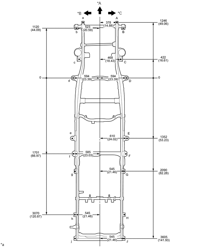
| *A | FRONT | *B | LH |
| *C | RH | - | - |
| *a | mm (in.) |
- | - |
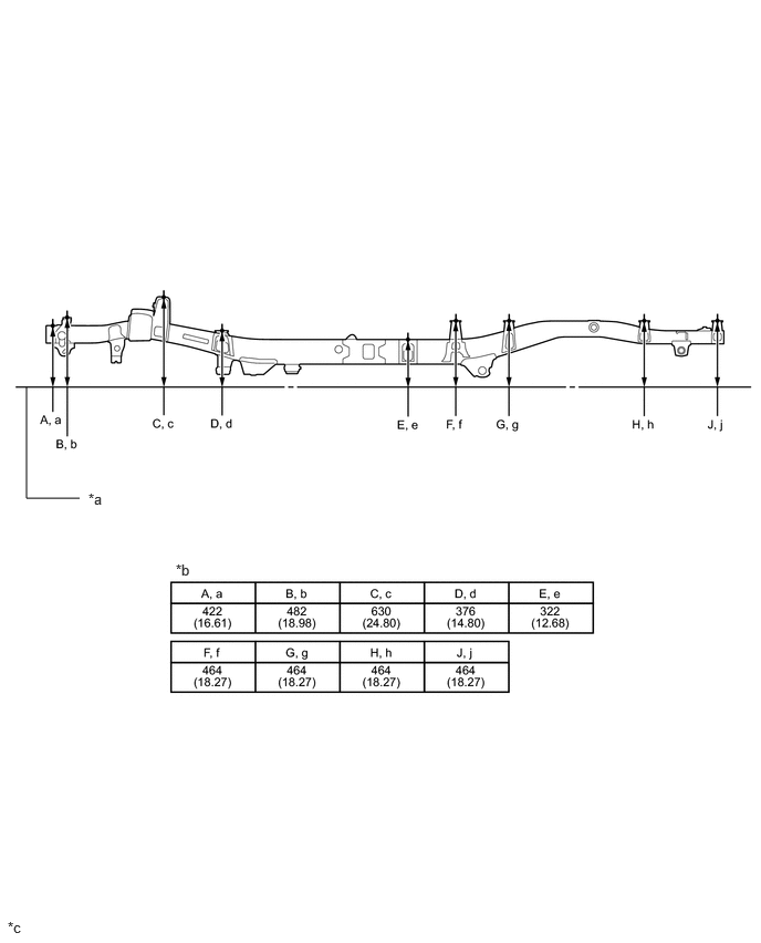
| *a | Imaginary Datum Line | *b | Height from Imaginary Datum Line |
| *c | mm (in.) |
- | - |
Lower Face
- HINT:
-
·
Length measurements are indicated at the points where the arrows extending from the zero point intersect the lines that extend towards the outside of the illustration from each point.
·In cases in which only one dimension is given, left and right are symmetrical.
·For symbols, capital letters indicate right side of vehicle, small letters indicate left side of vehicle (seen from rear).
| Symbol | Name | Hole Diameter mm (in.) |
|---|---|---|
| A, a | Front Bumper Side Mounting Bracket Installation Hole | φ14 (0.55) |
| B | Lateral Control Rod Installation Hole | φ16.5 (0.65) |
| C, c | Front Stabilizer Bracket Installation Nut | M8 (0.31) |
| D, d | Leading Arm Installation Hole | φ18.5 (0.73) |
| E, e | Rear Spring Bracket Pin Installation Hole | φ14 (0.55) |
| F, f | Rear Spring Bumper Installation Nut | M8 (0.31) |
| G, g | Spring Shackle Installation Hole | φ40 (1.57) |
| Wheel Base | 3180 mm (125.20 in.) |
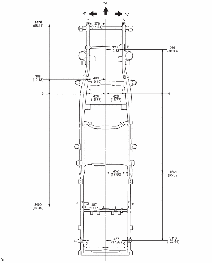
| *A | FRONT | *B | LH |
| *C | RH | - | - |
| *a | mm (in.) |
- | - |
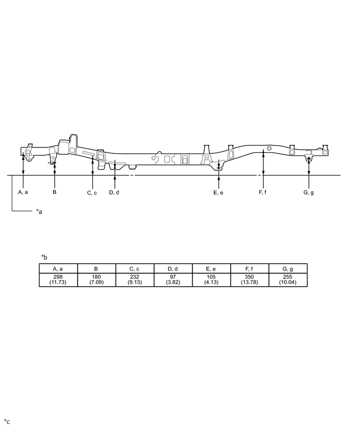
| *a | Imaginary Datum Line | *b | Height from Imaginary Datum Line |
| *c | mm (in.) |
- | - |
for 2 Door Short Van
Upper Face
- HINT:
-
·
Length measurements are indicated at the points where the arrows extending from the zero point intersect the lines that extend towards the outside of the illustration from each point.
·In cases in which only one dimension is given, left and right are symmetrical.
·For symbols, capital letters indicate right side of vehicle, small letters indicate left side of vehicle (seen from rear).
| Symbol | Name | Hole Diameter mm (in.) |
|---|---|---|
| A, a | Front Bumper Side Mounting Bracket Installation Hole | φ14 (0.55) |
| B, b | Body Mounting Hole | φ24 (0.94) |
| C, c | Shock Absorber Installation Hole | φ24 (0.94) |
| D, d | Body Mounting Hole | φ24 (0.94) |
| E, e | Body Mounting Hole | φ24 (0.94) |
| F, f | Body Mounting Hole | φ24 (0.94) |
| Wheel Base | 2310 mm (90.94 in.) |
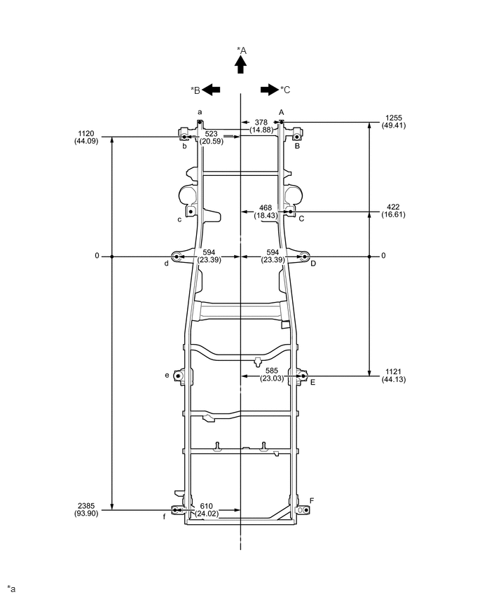
| *A | FRONT | *B | LH |
| *C | RH | - | - |
| *a | mm (in.) |
- | - |
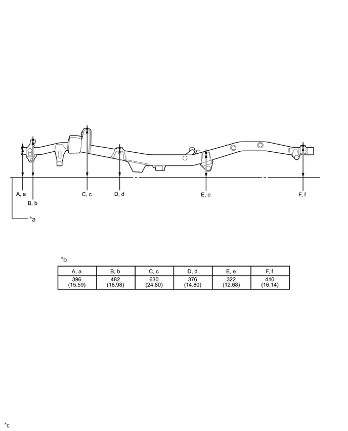
| *a | Imaginary Datum Line | *b | Height from Imaginary Datum Line |
| *c | mm (in.) |
- | - |
Lower Face
- HINT:
-
·
Length measurements are indicated at the points where the arrows extending from the zero point intersect the lines that extend towards the outside of the illustration from each point.
·In cases in which only one dimension is given, left and right are symmetrical.
·For symbols, capital letters indicate right side of vehicle, small letters indicate left side of vehicle (seen from rear).
| Symbol | Name | Hole Diameter mm (in.) |
|---|---|---|
| A, a | Front Bumper Side Mounting Bracket Installation Hole | φ13 (0.51) |
| B, b | Lateral Control Rod Installation Hole | φ16.5 (0.65) |
| C, c | Front Stabilizer Bracket Installation Nut | M8 (0.31) |
| D, d | Leading Arm Installation Hole | φ18.5 (0.73) |
| E, e | Rear Spring Bracket Pin Installation Hole | φ14 (0.55) |
| F, f | Rear Spring Bumper Installation Nut | M8 (0.31) |
| G, g | Spring Shackle Installation Hole | φ40 (1.57) |
| Wheel Base | 2310 mm (90.94 in.) |
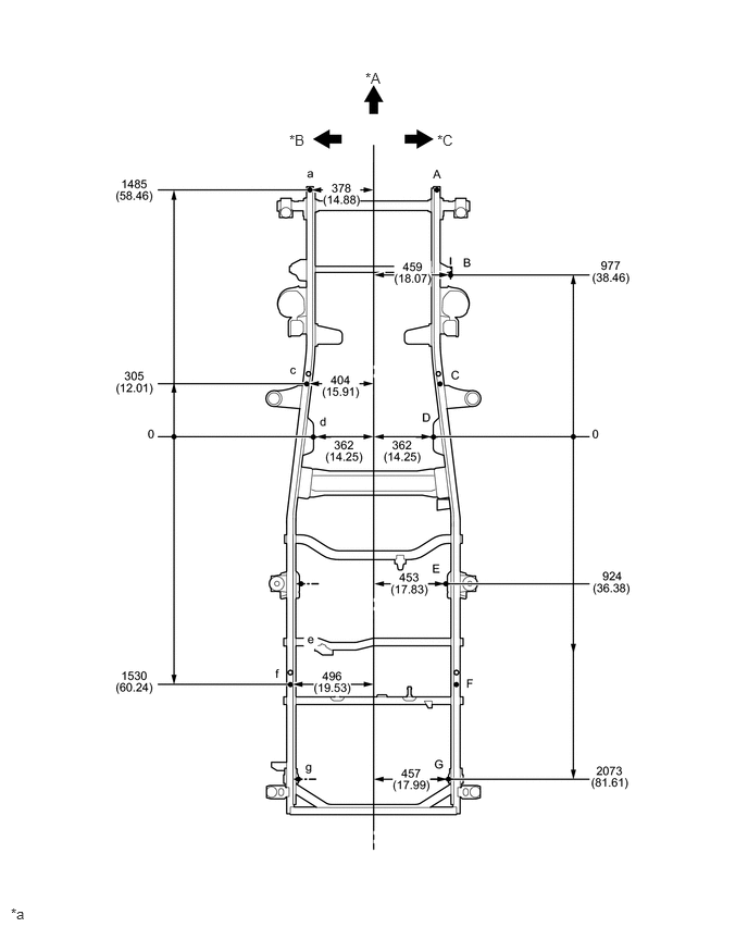
| *A | FRONT | *B | LH |
| *C | RH | - | - |
| *a | mm (in.) |
- | - |
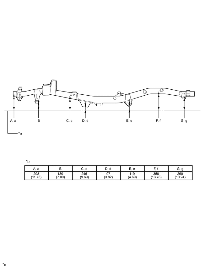
| *a | Imaginary Datum Line | *b | Height from Imaginary Datum Line |
| *c | mm (in.) |
- | - |
for 2 Door Long Van
Upper Face
- HINT:
-
·
Length measurements are indicated at the points where the arrows extending from the zero point intersect the lines that extend towards the outside of the illustration from each point.
·In cases in which only one dimension is given, left and right are symmetrical.
·For symbols, capital letters indicate right side of vehicle, small letters indicate left side of vehicle (seen from rear).
| Symbol | Name | Hole Diameter mm (in.) |
|---|---|---|
| A, a | Front Bumper Side Mounting Bracket Installation Hole | φ14 (0.55) |
| B, b | Body Mounting Hole | φ24 (0.94) |
| C, c | Shock Absorber Installation Hole | φ24 (0.94) |
| D, d | Body Mounting Hole | φ24 (0.94) |
| E, e | Body Mounting Hole | φ24 (0.94) |
| F, f | Body Mounting Hole | φ24 (0.94) |
| G, g | Body Mounting Hole | φ24 (0.94) |
| H, h | Body Mounting Hole | φ24 (0.94) |
| Wheel Base | 2980 mm (117.32 in.) |
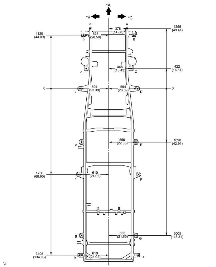
| *A | FRONT | *B | LH |
| *C | RH | - | - |
| *a | mm (in.) |
- | - |
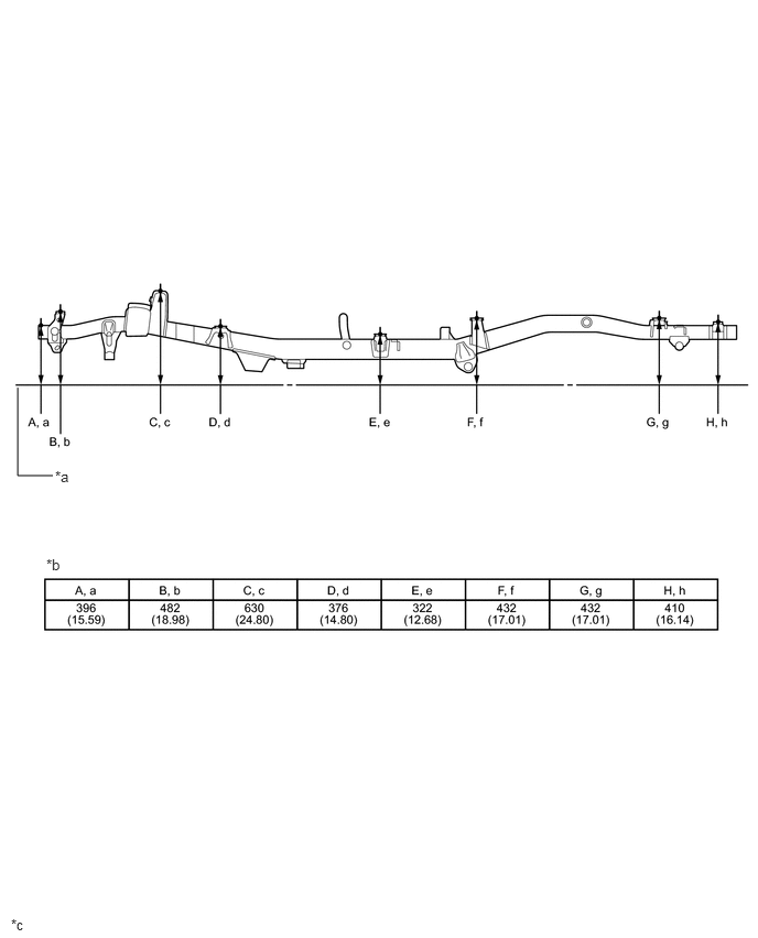
| *a | Imaginary Datum Line | *b | Height from Imaginary Datum Line |
| *c | mm (in.) |
- | - |
Lower Face
- HINT:
-
·
Length measurements are indicated at the points where the arrows extending from the zero point intersect the lines that extend towards the outside of the illustration from each point.
·In cases in which only one dimension is given, left and right are symmetrical.
·For symbols, capital letters indicate right side of vehicle, small letters indicate left side of vehicle (seen from rear).
| Symbol | Name | Hole Diameter mm (in.) |
|---|---|---|
| A, a | Front Bumper Side Mounting Bracket Installation Hole | φ13 (0.51) |
| B | Lateral Control Rod Installation Hole | φ16.5 (0.65) |
| C, c | Front Stabilizer Bracket Installation Nut | M8 (0.31) |
| D, d | Leading Arm Installation Hole | φ18.5 (0.73) |
| E, e | Rear Spring Bracket Pin Installation Hole | φ14 (0.55) |
| F, f | Rear Spring Bumper Installation Nut | M8 (0.31) |
| G, g | Spring Shackle Installation Hole | φ40 (1.57) |
| Wheel Base | 2980 mm (117.32 in.) |
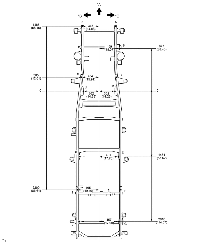
| *A | FRONT | *B | LH |
| *C | RH | - | - |
| *a | mm (in.) |
- | - |
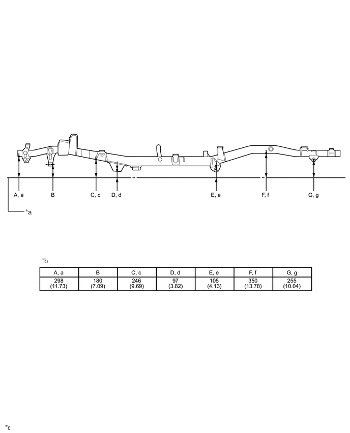
| *a | Imaginary Datum Line | *b | Height from Imaginary Datum Line |
| *c | mm (in.) |
- | - |
for 4 Door Van
Upper Face
- HINT:
-
·
Length measurements are indicated at the points where the arrows extending from the zero point intersect the lines that extend towards the outside of the illustration from each point.
·In cases in which only one dimension is given, left and right are symmetrical.
·For symbols, capital letters indicate right side of vehicle, small letters indicate left side of vehicle (seen from rear).
| Symbol | Name | Hole Diameter mm (in.) |
|---|---|---|
| A, a | Front Bumper Side Mounting Bracket Installation Hole | φ14 (0.55) |
| B, b | Body Mounting Hole | φ24 (0.94) |
| C, c | Shock Absorber Installation Hole | φ24 (0.94) |
| D, d | Body Mounting Hole | φ24 (0.94) |
| E, e | Body Mounting Hole | φ24 (0.94) |
| F, f | Body Mounting Hole | φ24 (0.94) |
| G, g | Body Mounting Hole | φ24 (0.94) |
| Wheel Base | 2730 mm (107.48 in.) |
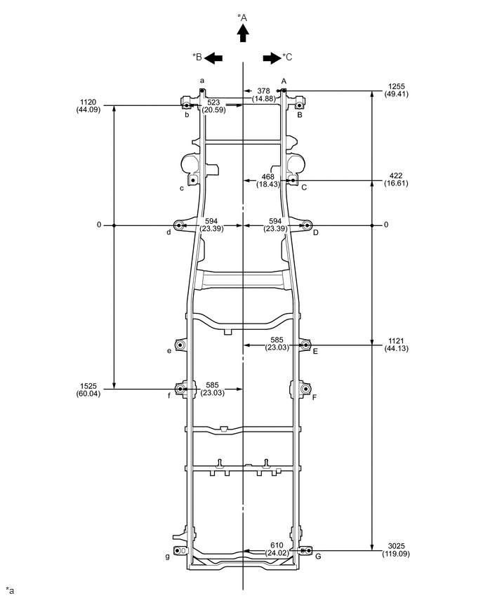
| *A | FRONT | *B | LH |
| *C | RH | - | - |
| *a | mm (in.) |
- | - |
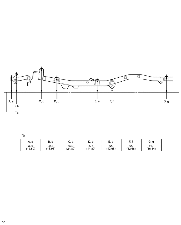
| *a | Imaginary Datum Line | *b | Height from Imaginary Datum Line |
| *c | mm (in.) |
- | - |
Lower Face
- HINT:
-
·
Length measurements are indicated at the points where the arrows extending from the zero point intersect the lines that extend towards the outside of the illustration from each point.
·In cases in which only one dimension is given, left and right are symmetrical.
·For symbols, capital letters indicate right side of vehicle, small letters indicate left side of vehicle (seen from rear).
| Symbol | Name | Hole Diameter mm (in.) |
|---|---|---|
| A, a | Front Bumper Side Mounting Bracket Installation Hole | φ13 (0.51) |
| B | Lateral Control Rod Installation Hole | φ16.5 (0.65) |
| C, c | Front Stabilizer Bracket Installation Nut | M8 (0.31) |
| D, d | Leading Arm Installation Hole | φ18.5 (0.73) |
| E, e | Rear Spring Bracket Pin Installation Hole | φ14 (0.55) |
| F, f | Rear Spring Bumper Installation Nut | M8 (0.31) |
| G, g | Spring Shackle Installation Hole | φ40 (1.57) |
| Wheel Base | 2730 mm (107.48 in.) |
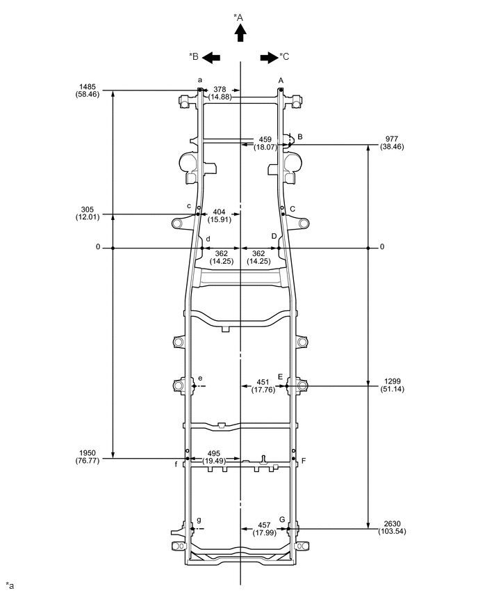
| *A | FRONT | *B | LH |
| *C | RH | - | - |
| *a | mm (in.) |
- | - |
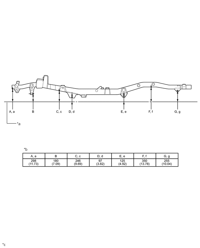
| *a | Imaginary Datum Line | *b | Height from Imaginary Datum Line |
| *c | mm (in.) |
- | - |