INTRODUCTION WHEN REMOVING,INSTALLING OR REPLACING PARTS WHEEL ALIGNMENT STANDARD
MEASURE VEHICLE HEIGHT
- NOTICE:
-
·
Before inspecting the wheel alignment, adjust the vehicle height to the specification.
·The standard value shown here is a value that is used for adjusting the wheel alignment and does not indicate the height of an actual vehicle.
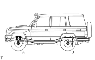
Press down on the vehicle several times to stabilize the suspension, and then measure the vehicle height.
- Standard Vehicle Height (Unloaded Vehicle):
-
Body Type A (Front) B (Rear) Short 27 mm (1.06 in.) 105 mm (4.13 in.) Semi Long 34 mm (1.34 in.) 83 mm (3.27 in.) Long 34 mm (1.34 in.) 113 mm (4.45 in.) Super Long
Single Cab
Standard Suspension Type33 mm (1.30 in.) 130 mm (5.12 in.) Super Long
Single Cab
Hard Duty Suspension Type22 mm (0.87 in.) 132 mm (5.20 in.) Super Long
Double Cab
Standard Suspension Type35 mm (1.38 in.) 108 mm (4.25 in.) Super Long
Double Cab
Hard Duty Suspension Type25 mm (0.98 in.) 110 mm (4.33 in.)
- Measuring points:
- A:
-
Distance from the front axle housing to the follow spring
- B:
-
Distance from the rear axle housing to the bumper stopper
If the vehicle height is not as specified, adjust the height by pressing down on the vehicle several times to stabilize the suspension.
INSPECT CAMBER, CASTER AND STEERING AXIS INCLINATION (FRONT WHEEL ALIGNMENT)
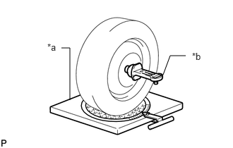
| *a | Alignment Tester |
| *b | Gauge |
Install a camber-caster-kingpin gauge or place the front wheels on the center of a wheel alignment tester.
Inspect the camber, caster and steering axis inclination.
- Standard Camber, Caster and Steering Axis Inclination (Unloaded Vehicle):
-
Item Specified Condition Camber
Right-left error1°00' +/-45' (1.00° +/-0.75°)
45' (0.75°) or lessCaster
Right-left errorExcept Super Long 4°20' +/-60' (4.33° +/-1.00°)
45' (0.75°) or lessSuper Long 3°35' +/-60' (3.58° +/-1.00°)
45' (0.75°) or lessSteering axis inclination 13°00' +/-45' (13.00° +/-0.75°)
If the caster and steering axis inclination are not as specified after the camber has been correctly adjusted, recheck the suspension parts for damage and/or wear.
INSPECT TOE-IN (FRONT WHEEL ALIGNMENT)
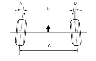

|
Front of the Vehicle |
If the toe-in is not as specified, adjust the tie rod ends.
- Standard Toe-in (Unloaded Vehicle):
-
A + B
C - DA + B: 0°00' +/-12' (0.00° +/-0.2°)
C - D: 0 +/-2 mm (0.00 +/-0.0787 in.)
INSPECT WHEEL ANGLE (FRONT WHEEL ALIGNMENT)
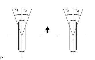
| *a | Inside |
| *b | Outside |
|
|
Front of the Vehicle |
Turn the steering wheel fully, and measure the wheel angle.
- Standard Wheel Angle (Unloaded Vehicle):
-
Inside wheel angle Outside wheel angle (reference) 29°00' to 32°00' (29.00° to 32.00°) 28°00' (28.00°)
- NOTICE:
-
When the steering wheel is fully turned, make sure that the wheel is not touching the body or brake flexible hose. If the maximum wheel angle differs from the standard value, adjust the wheel angle with the knuckle stopper bolts.
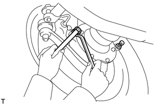
Adjust the wheel angle.
Loosen the lock nuts and adjust the wheel angle using the knuckle stopper bolts.
- NOTICE:
-
The stopper bolts are installed to the front and back of the left and right side steering knuckles. When performing adjustments, the rear right side and front left side stopper bolts are considered to be a pair and the rear left side and front right side stopper bolts are considered to be a pair. When adjusting either of these bolt pairs, make sure that both of the stopper bolts are turned until they stop at the same time. After adjusting the wheel angle, there should not be any clearance between either of the bolts and the adjacent bracket.
If the wheel angle still cannot be adjusted to the standard value, inspect the steering parts and replace any damaged or worn parts as necessary.
Tighten the lock nuts.
- Torque:
- 44.1 N*m (450 kgf*cm, 33 ft.*lbf)