Home › Engine / Hybrid System › 1GR-FE (ENGINE CONTROL) › SFI SYSTEM
NM25T0E _51 Engine / Hybrid System _029291 1GR-FE ENGINE CONTROL _0137811 SFI SYSTEM DE DETAILS F

1GR-FE ENGINE CONTROL  SFI SYSTEM  DETAILS  CRANKSHAFT POSITION SENSOR AND CAMSHAFT POSITION SENSOR  


CONSTRUCTION


a.

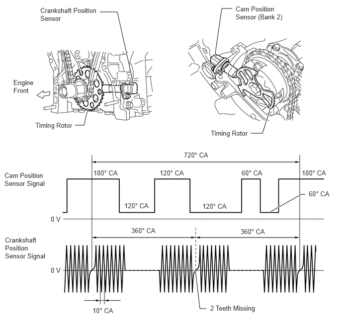
A pick-up coil type crankshaft position sensor is used. The timing rotor of the crankshaft consists of 34 teeth, with 2 teeth missing. The crankshaft position sensor outputs the crankshaft rotation signals every 10°, and the missing teeth are used to determine the top-dead-center.


b.

A Magnetic Resistance Element (MRE) type cam position sensor is used. To detect the camshaft position, a timing rotor that is secured to the camshaft in front of the VVT controller is used to generate 3 (3 high output, 3 low output) pulses for every 2 revolutions of the crankshaft.
W104344E03
2.802,1.792 2.458,0.25 2.458,0.25 2.094,0.25 true 1.844,2.26 1.76,2.625 1.76,2.625 1.573,2.625 true 5.667,2.26 5.5,2.792 5.5,2.792 5.25,2.792 true 4.5,1.188 4.646,0.177 4.646,0.177 4.865,0.177 true 4.094,5.667 4.188,6.469 4.188,6.469 4.323,6.469 true 5.667,4.438 6.313,4.073 6.313,4.073 6.396,4.073 true 0.281,1.646 0.74,2.313 0.458,0.667 10 false Engine Front 0.74,2.542 1.573,2.917 0.833,0.375 10 false Timing Rotor 0.844,0.135 2.063,0.75 1.219,0.615 10 false Crankshaft Position Sensor 4.938,0.104 5.99,0.521 1.052,0.417 10 false Cam Position Sensor (Bank 2) 4.417,2.708 5.271,3.094 0.854,0.385 10 false Timing Rotor 3.854,3.167 4.479,3.51 0.625,0.344 10 false 720° CA 1.958,3.542 2.583,3.885 0.625,0.344 10 false 180° CA 6.323,3.542 6.948,3.885 0.625,0.344 10 false 180° CA 2.604,4.229 3.229,4.573 0.625,0.344 10 false 120° CA 3.344,3.542 3.969,3.885 0.625,0.344 10 false 120° CA 4.24,4.24 4.865,4.583 0.625,0.344 10 false 120° CA 5.063,3.542 5.688,3.885 0.625,0.344 10 false 60° CA 6.469,3.979 7.094,4.323 0.625,0.344 10 false 60° CA 5.042,4.771 5.667,5.115 0.625,0.344 10 false 360° CA 2.75,4.75 3.375,5.094 0.625,0.344 10 false 360° CA 1.938,6.427 2.563,6.771 0.625,0.344 10 false 10° CA 1.063,4.51 1.354,4.823 0.292,0.313 10 false 0 V 1.063,5.583 1.354,5.896 0.292,0.313 10 false 0 V 4.406,6.375 5.458,6.708 1.052,0.333 10 false 2 Teeth Missing 0.104,4.948 0.99,6.01 0.885,1.063 10 false Crankshaft Position Sensor Signal 0.094,3.594 0.99,4.01 0.896,0.417 10 false Cam Position Sensor Signal


c.

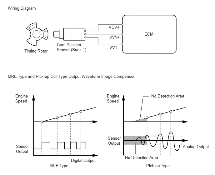
The MRE type cam position sensor consists of an MRE, a magnet and a sensor. The direction of the magnetic field changes due to the different shapes (protruded and non-protruded portions) of the timing rotor, which passes by the sensor. As a result, the resistance of the MRE changes, and the output voltage to the ECM changes to high or low. The ECM detects the camshaft position based on this output voltage.
W100681E18
4.521,4.771 4.521,5.146 true 4.667,3.969 4.771,3.208 4.771,3.208 4.958,3.208 true 0.26,0.188 1.594,0.646 1.333,0.458 10 false Wiring Diagram 0.26,2.458 4.823,2.76 4.563,0.302 10 false MRE Type and Pick-up Coil Type Output Waveform Image Comparison 0.813,1.615 1.74,2 0.927,0.385 10 false Timing Rotor 1.896,1.406 3.042,1.917 1.146,0.51 10 false Cam Position Sensor (Bank 1) 3.625,0.823 4.042,1.167 0.417,0.344 10 false VCV+ 3.646,1.156 4.031,1.49 0.385,0.333 10 false VV1+ 3.646,1.5 4.042,1.833 0.396,0.333 10 false VV1- 4.813,1.052 5.26,1.385 0.448,0.333 10 false ECM 0.51,3.115 0.969,3.833 0.458,0.719 10 false Engine Speed 3.563,3.115 4.021,3.833 0.458,0.719 10 false Engine Speed 0.531,4.792 1,5.521 0.469,0.729 10 false Sensor Output 3.594,4.521 4.063,5.25 0.469,0.729 10 false Sensor Output 1.646,5.438 2.427,5.823 0.781,0.385 10 false MRE Type 4.875,5.438 6,5.823 1.125,0.385 10 false Pick-up Type 2.365,5.26 3.313,5.625 0.948,0.365 10 false Digital Output 6.094,4.802 7.104,5.229 1.01,0.427 10 false Analog Output 4.167,5.167 5.365,5.5 1.198,0.333 10 false No Detection Area 5.042,3.115 6.24,3.448 1.198,0.333 10 false No Detection Area