1HZ FUEL FUEL SYSTEM DETAILS INJECTION PUMP
CONSTRUCTION
A compact and lightweight distributor type injection pump assembly is used.
The following devices are used for the injection pump assembly depending on the model.
| Device | Function |
|---|---|
| Engine Speed Sensor | Detects the engine speed. |
| High Altitude Compensator | Compensates the injection volume in accordance with the altitude (atmospheric pressure). |
| Automatic Cold Start Device (ACSD) (Thermo Wax) | Improves low temperature startability. |
| Throttle Position Sensor | Detects the amount of pedal effort applied to the accelerator pedal. |
| Timing Control Valve (TCV) | Optimizes advanced characteristics of the timer for partial load regions. |
| Boost Altitude Compensation System (BACS) | Reduces black smoke which occurs due to sudden acceleration, etc., after having the EGR on. |
| Injection Pump Part No. | Device | |||||
|---|---|---|---|---|---|---|
| Engine Speed Sensor | High Altitude Compensator | ACSD | Throttle Position Sensor | TCV | BACS | |
| 22100-1C050 | ○ | - | - | - | - | - |
| 22100-1C190 | - | - | - | - | - | - |
| 22100-1C220 | - | - | - | - | - | - |
| 22100-1C201 | - | ○ | - | - | - | - |
| 22100-1C380 | ○ | ○ | - | - | - | - |
| 22100-1C461 | ○ | ○ | ○ | - | - | - |
| 22100-17A70 | ○ | - | ○ | ○ | ○ | ○ |
○: Applicable
-: Not applicable
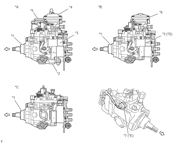
| *A | w/ BACS | *B | w/ High Altitude Compensator |
| *C | w/o BACS and High Altitude Compensator | *D | w/ ACSD |
| *E | w/ Engine Speed Sensor | - | - |
| *1 | Injection Pump Assembly | *2 | TCV |
| *3 | ACSD | *4 | BACS |
| *5 | Throttle Position Sensor | *6 | High Altitude Compensator |
| *7 | Engine Speed Sensor | - | - |
High Altitude Compensator*
*: Models with high altitude compensator
The high altitude compensator consists of bellows, a spill ring and linkage (push rod, connecting pin, control arm and governor lever). Bellows which expand and contract according to the atmospheric pressure are used to adjust the spill ring position and control the fuel injection volume according to the atmospheric pressure. Performing this control increases fuel efficiency at high altitudes and reduces black smoke.
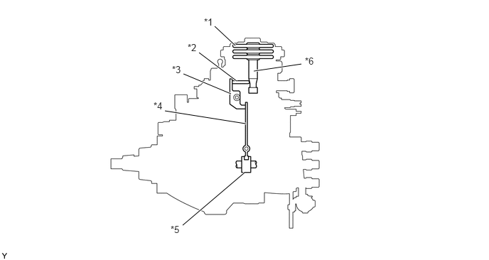
| *1 | Bellows | *2 | Connecting Pin |
| *3 | Control Arm | *4 | Governor Lever |
| *5 | Spill Ring | *6 | Push Rod |
ACSD*
*: Models with ACSD
Engine coolant circulates around the ACSD (thermo wax), which has thermo wax enclosed. The thermo wax expands or contracts depending on the engine coolant temperature. This movement rotates lever "A" to rotate the roller ring. Lever "A" normally pushes the timer piston to the advanced position according to the force of the return spring. Also, the movement of lever "A" rotates the adjusting lever via lever "B".
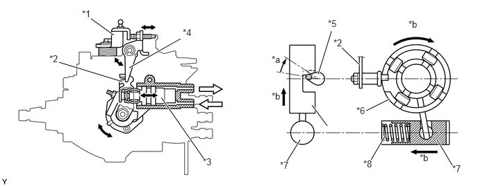
| *1 | Adjusting Lever | *2 | Lever "A" |
| *3 | Thermo Wax | *4 | Lever "B" |
| *5 | Cam | *6 | Roller Ring |
| *7 | Timer Piston | *8 | Timer Spring |
| *a | Lever "A" Rotation Amount | *b | Advanced |

|
Engine Coolant | - | - |
BACS*
*: Models with BACS
The BACS consists of a diaphragm chamber, push rod, spill ring and linkages. The fuel injection volume can be controlled by adjusting the position of the spill ring.
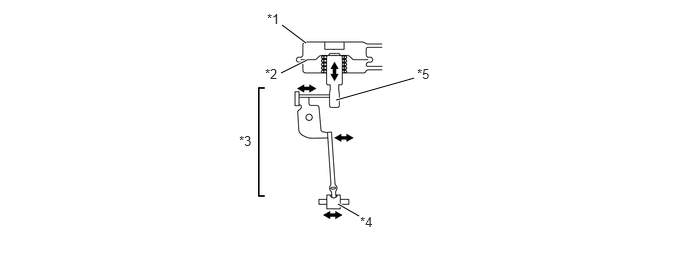
| *1 | Diaphragm Chamber | *2 | Diaphragm |
| *3 | Linkages | *4 | Spill Ring |
| *5 | Push Rod | - | - |
Engine Speed Sensor*
*: Models with engine speed sensor
The engine speed is detected by way of the flyweight gear teeth (37 teeth), which is driven by the drive shaft of the injection pump, and the pick-up coil of the engine speed sensor.
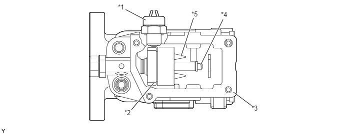
| *1 | Engine Speed Sensor | *2 | Drive Gear |
| *3 | Pump Body | *4 | Drive Shaft |
| *5 | Flyweight | - | - |
OPERATION
Basic Operation
The centrifugal force type feed pump takes up a fixed volume of fuel with each turn. The fuel expulsion pressure from the feed pump is controlled by operation of the pressure regulator valve.
Fuel is sent from the outside of the feed pump, through the hole in the upper part of the feed pump cover and into the pump body.
The pump plunger also rotates as it moves up and down. After the fuel is drawn in, it is distributed under pressure to the delivery valve of each cylinder according to the injection order.
The centrifugal force type all speed governor installed in the upper part of the injection pump assembly moves the spill ring obstructing the plunger spill port and controls the fuel injection volume.
The hydraulic type timer installed in the lower part of the injection pump assembly is operated by the fuel pressure of the pump housing, and movement of the roller ring by the timer advances the injection angle and controls the injection timing.
The fuel cut solenoid valve is connected to the ignition switch circuit, and when the ignition switch is turned off, the current is cut off, the solenoid is de-energized, fuel is cut off and the engine stops.
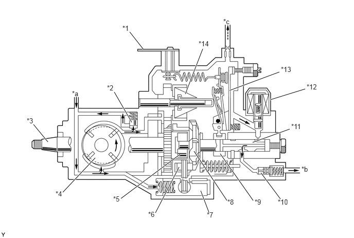
| *1 | Adjusting Lever | *2 | Regulator Valve |
| *3 | Drive Shaft | *4 | Feed Pump |
| *5 | Coupling | *6 | Roller |
| *7 | Timer Piston | *8 | Face Camplate |
| *9 | Spill ring | *10 | Delivery Valve |
| *11 | Pump Plunger | *12 | Fuel Cut Solenoid Valve |
| *13 | Governor Lever | *14 | Flyweight |
| *a | Fuel from Fuel Filter | *b | Fuel to Injection Pump |
| *c | Fuel to Overflow Pipe | - | - |
High Altitude Compensator
When Driving on Level Surface
Since the bellows do not expand and the spill ring is at the normal position, the fuel injection volume is normal.
When Driving at High Elevations
The bellows expand, moving the push rod to move the spill ring in the fuel injection volume reduction direction via the linkage. This movement causes the fuel injection volume to decrease.
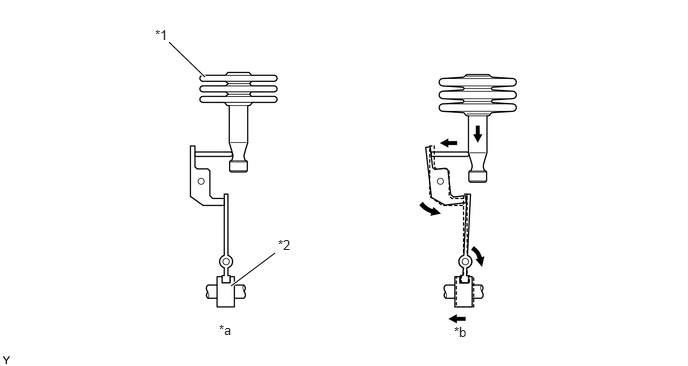
| *1 | Bellows | *2 | Spill Ring |
| *a | When Driving on Level Surface | *b | When Driving at High Elevations |
ACSD
When the engine coolant temperature is low, the thermo wax contracts and lever "A" rotates in the clockwise direction by the force of the return spring. Since the force of the return spring is stronger than the force of the timer spring, lever "A" moves the roller ring and timer piston inside the injection pump assembly in the advanced direction while at the same time pushing the adjusting lever via lever "B" to perform idle up.
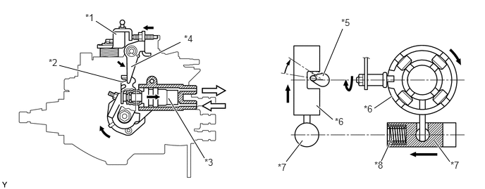
| *1 | Adjusting Lever | *2 | Lever "A" |
| *3 | Thermo Wax | *4 | Lever "B" |
| *5 | Cam | *6 | Roller Ring |
| *7 | Timer Piston | *8 | Timer Spring |
|
|
Engine Coolant | - | - |
When the engine coolant temperature rises, the thermo wax expands, rotating lever "A" in the counterclockwise direction. This rotation makes the timer spring push and move the timer piston in the retarded direction, rotate the roller ring in the retarded direction and cancels the movement in the advanced direction when the engine starts. At the same time, the adjusting lever moves to its original position and cancels idle up.
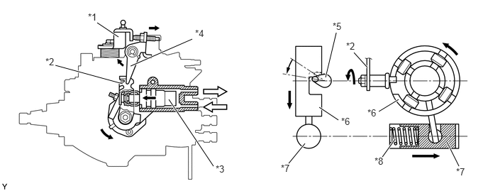
| *1 | Adjusting Lever | *2 | Lever "A" |
| *3 | Thermo Wax | *4 | Lever "B" |
| *5 | Cam | *6 | Roller Ring |
| *7 | Timer Piston | *8 | Timer Spring |
|
|
Engine Coolant | - | - |
TCV
For details of TCV operation, see the EMISSION CONTROL (1HZ) section.
Engine / Hybrid System>1HZ EMISSION CONTROL>EMISSION CONTROL SYSTEM>TCV CONTROL
BACS
For details of BACS operation, see the EMISSION CONTROL (1HZ) section.
Engine / Hybrid System>1HZ EMISSION CONTROL>EMISSION CONTROL SYSTEM>BACS CONTROL