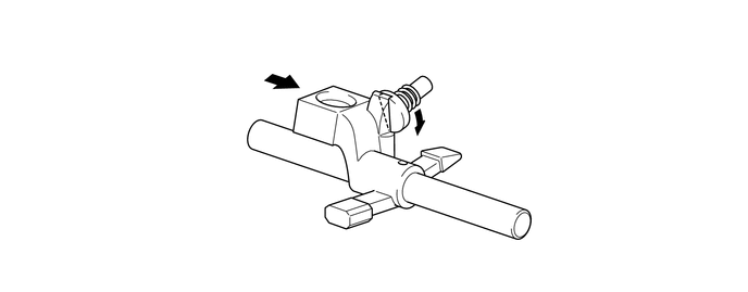
H150F MANUAL TRANSMISSION / TRANSAXLE MANUAL TRANSMISSION SYSTEM DETAILS SHIFT AND SELECT
CONSTRUCTION
A shaft slide type with 4 shift fork shafts is used.
An aluminum die-cast No. 1 gear shift fork, No. 2 gear shift fork, No.3 gear shift fork and reverse shift fork with superior anti-friction performance are used.
A reverse mis-shift prevention mechanism and a reverse 1-way mechanism have been provided to ensure reliability.
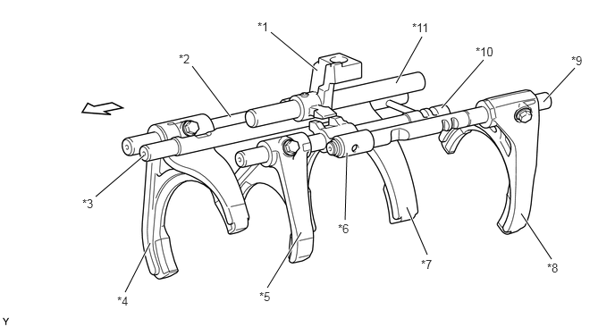
| *1 | Shift Lever Housing | *2 | No. 2 Gear Shift Fork Shaft |
| *3 | No. 1 Gear Shift Fork Shaft | *4 | No. 2 Gear Shift Fork |
| *5 | No. 3 Gear Shift Fork | *6 | Reverse Shift Head |
| *7 | No. 1 Gear Shift Fork | *8 | Reverse Shift Fork |
| *9 | No. 4 Gear Shift Fork Shaft | *10 | No. 3 Gear Shift Fork Shaft |
| *11 | Shift and Select Lever Shaft | - | - |

|
Engine Side | - | - |
OPERATION
Reverse 1-way Mechanism
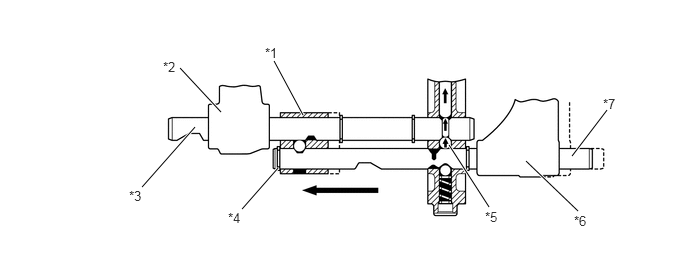
The reverse 1-way mechanism is a function that operates the reverse shift fork only when shifting to reverse and that stops the reverse shift fork in neutral position when moving the shift lever to 5th.
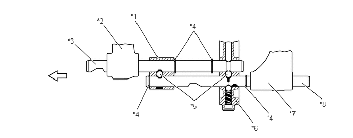
| *1 | Reverse Shift Head | *2 | No. 3 Gear Shift Fork |
| *3 | No. 3 Gear Shift Fork Shaft | *4 | Snap Ring |
| *5 | Shift Interlock Ball | *6 | Transmission Intermediate Plate |
| *7 | Reverse Shift Fork | *8 | No. 4 Gear Shift Fork Shaft |
|
|
Engine Side | - | - |
When moving the shift lever to 5th, using the snap ring with the reverse shift head engaged with the No. 3 gear shift fork shaft, the No. 3 gear shift fork moves to the right. At this time, the shift interlock ball fits into the groove of the No. 4 gear shift fork shaft so that the reverse shift fork does not move.
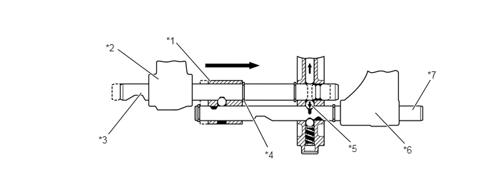
| *1 | Reverse Shift Head | *2 | No. 3 Gear Shift Fork |
| *3 | No. 3 Gear Shift Fork Shaft | *4 | Snap Ring |
| *5 | Shift Interlock Ball | *6 | Reverse Shift Fork |
| *7 | No. 4 Gear Shift Fork Shaft | - | - |
When moving the shift lever to R, using the snap ring with the reverse shift head engaged with the No. 4 gear shift fork shaft, the reverse shift fork moves to the left. At this time, similarly to when moving the shift lever to 5th, the shift interlock ball fits into the groove of the No. 3 gear shift fork shaft so that the No. 3 gear shift fork does not move.
| *1 | Reverse Shift Head | *2 | No. 3 Gear Shift Fork |
| *3 | No. 3 Gear Shift Fork Shaft | *4 | Snap Ring |
| *5 | Shift Interlock Ball | *6 | Reverse Shift Fork |
| *7 | No. 4 Gear Shift Fork Shaft | - | - |
Reverse Mis-shift Prevention Mechanism
This mechanism is designed to prevent directly shifting to reverse from 5th gear while driving.
- HINT:
-
When shifting to reverse, the shift lever is momentarily moved back to N before shifting is performed.
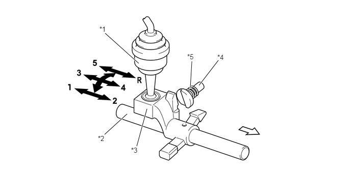
| *1 | Transmission Shift Lever Assembly | *2 | Shift and Select Lever Shaft |
| *3 | Shift Lever Housing | *4 | No. 1 Reverse Restrict Pin |
| *5 | Spring (Reverse Restrict Pin Compression spring) | - | - |
|
|
Engine Side |

|
Shift Lever Housing Movement Direction |
If the shift lever is moved towards 5th and R, the shift lever housing rotates, pushing in the spring to push the reverse restrict pin.
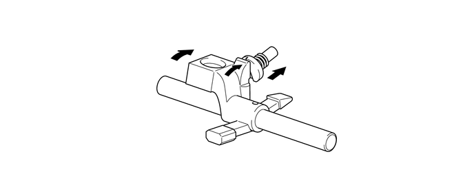
If the shift lever is moved completely to 5th, the shift lever housing slides backward. Due to this, the No. 1 reverse restrict pin is detached from the shift lever housing and returns to the original position using the force of the spring.
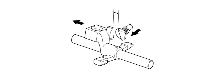
When trying to move the shift lever from 5th directly to R, the shift lever housing contacts the cutout of the No. 1 reverse restrict pin, preventing an erroneous shift operation into reverse.