H150F MANUAL TRANSMISSION / TRANSAXLE MANUAL TRANSMISSION SYSTEM DETAILS GEAR TRAIN
CONSTRUCTION
Gear Layout
The gear layout is a 4th gear direct coupling and 5th gear overdrive type, as in the constant mesh type.
The 5th gear has been positioned near the center between the manual transmission case support and transmission intermediate plate support. Due to this, the load placed on the output shaft and counter gear when using 5th gear is distributed to the left and right bearings, reducing the load for each bearing.
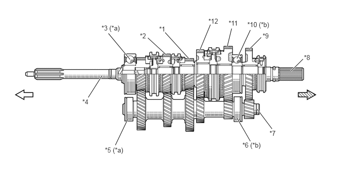
| *1 | 5th Gear | *2 | 3rd Gear |
| *3 | Front Input Shaft Bearing | *4 | Input Shaft |
| *5 | Front Counter Gear Bearing or Roller | *6 | Center Counter Shaft Bearing |
| *7 | Counter Gear | *8 | Output Shaft |
| *9 | Reverse Gear | *10 | Rear Output Shaft Bearing |
| *11 | 1st Gear | *12 | 2nd Gear |
| *a | Manual Transmission Case Support | *b | Transmission Intermediate Plate Support |

|
Engine Side |

|
Wheel Side |
Bearing
An input shaft bearing and output shaft bearing are used for the sealed ball bearing to ensure sufficient durability.
A cylindrical roller bearing with a large load capacity of the counter gear has ensured sufficient support rigidity and durability.
A needle roller bearing is used for each gear.
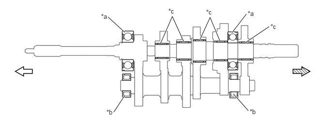
| *a | Sealed Ball Bearing | *b | Cylindrical Roller Bearing |
| *c | Needle Roller Bearing | - | - |
|
|
Engine Side |
|
Wheel Side |
Gear
High-tooth gears are used for all the gears. Due to this, a maximized contact ratio for the gear has been ensured, achieving gear noise reduction.
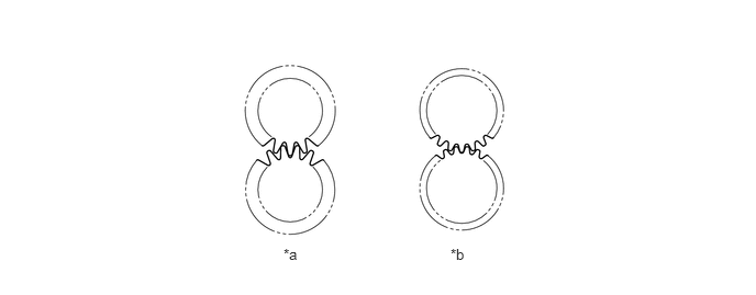
| *a | High-tooth Gear | *b | Normal Gear |
OPERATION
Gear Train Operation (1st)
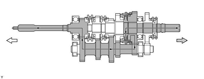
|
|
Engine Side |
|
Wheel Side |
Gear Train Operation (2nd)
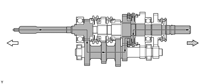
|
|
Engine Side |
|
Wheel Side |
Gear Train Operation (3rd)
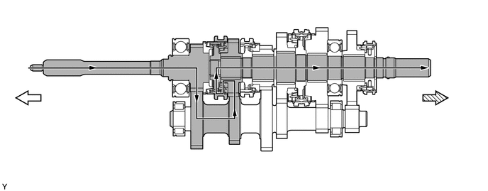
|
|
Engine Side |
|
Wheel Side |
Gear Train Operation (4th)
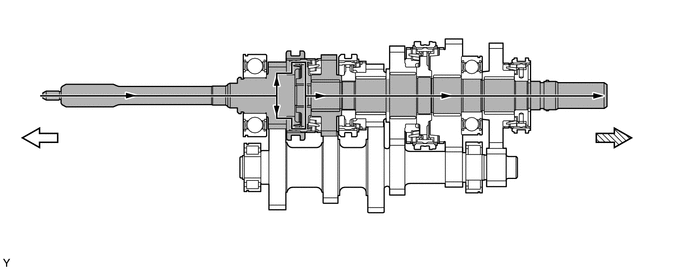
|
|
Engine Side |
|
Wheel Side |
Gear Train Operation (5th)
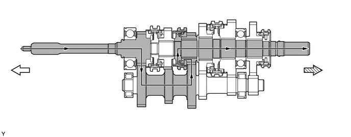
|
|
Engine Side |
|
Wheel Side |
Gear Train Operation (Reverse)
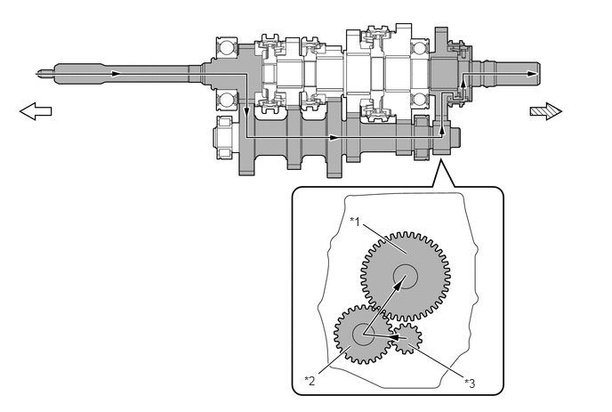
| *1 | Reverse Gear | *2 | Reverse Idler Gear |
| *3 | Counter Gear | - | - |
|
|
Engine Side |
|
Wheel Side |