BRAKE CONTROL / DYNAMIC CONTROL SYSTEMS BRAKE CONTROL SYSTEM DETAILS BRAKE ACTUATOR
CONSTRUCTION
A brake actuator with an integrated skid control ECU is used.
A solenoid relay and motor relay are built into the skid control ECU.
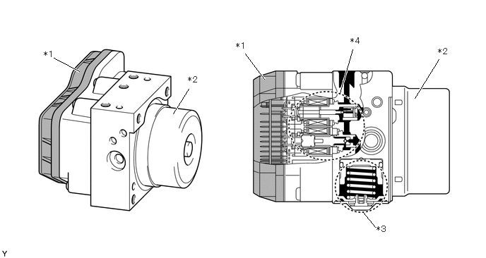
| *1 | Skid Control ECU Section
·
Solenoid Relay
·
Motor Relay |
*2 | Pump Motor Section |
| *3 | Reservoir Section | *4 | Solenoid Valve Section |
The brake actuator assembly consists of 6 two-position solenoid valves, 1 motor, 2 pumps and 2 reservoirs. The 6 two-position solenoid valves consist of 3 pressure holding valves [(1), (2), (3)] and 3 pressure reduction valves [(4), (5), (6)].
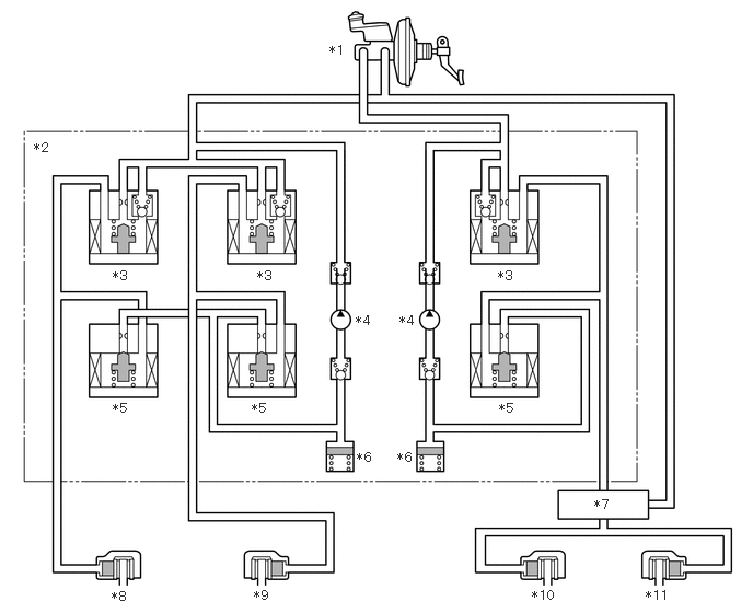
| *1 | Brake Master Cylinder Sub-assembly | *2 | Brake Actuator Assembly |
| *3 | Pressure Holding Valve | *4 | Pump |
| *5 | Pressure Reduction Valve | *6 | Reservoir |
| *7 | Load Sensing Proportioning Valve Assembly | *8 | Front Left Brake |
| *9 | Front Right Brake | *10 | Rear Left Brake |
| *11 | Rear Right Brake | - | - |
OPERATION
ABS
Based on the signals received from the 4 speed sensors, the skid control ECU calculates the speed of each wheel and deceleration, and checks the wheel slipping condition. In accordance with to the slipping condition, the skid control ECU controls the pressure holding valve and pressure reduction valve in order to adjust the fluid pressure of each wheel cylinder in the following 3 modes: pressure reduction, pressure holding, and pressure increase modes.
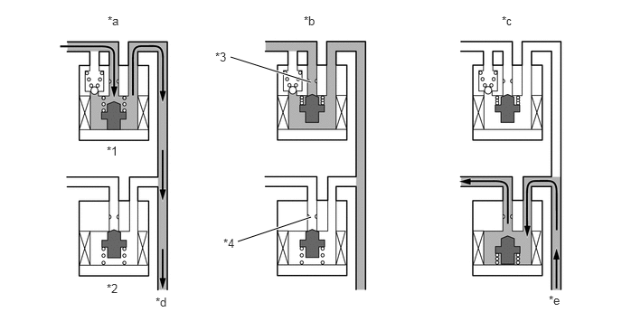
| *1 | Pressure Holding Solenoid Valve | *2 | Pressure Reduction Solenoid Valve |
| *3 | Port A | *4 | Port B |
| *a | Pressure Increase Mode | *b | Pressure Holding Mode |
| *c | Pressure Reduction Mode | *d | To Wheel Cylinder |
| *e | From Wheel Cylinder | - | - |
| Pressure Mode | Increase Mode | Holding Mode | Reduction Mode |
|---|---|---|---|
| Pressure Holding Solenoid Valve | Off | On | ← |
| Pressure Reduction Solenoid Valve | Off | ← | On |
| Port A | Open | Closed | ← |
| Port B | Closed | ← | Open |
| Wheel Cylinder Pressure | Increases | Holds | Reduces |