STEERING COLUMN STEERING COLUMN SYSTEM DETAILS ENERGY ABSORBING MECHANISM
CONSTRUCTION
The energy absorbing mechanism mainly consists of a No .2 steering intermediate shaft sub-assembly, break away bracket, break away capsule and steering column upper tube and steering column lower tube.
The steering column upper tube is mounted on the instrument panel reinforcement via the break away capsule and break away bracket. The steering column assembly and the power steering gear assembly are connected with a contractile No. 2 steering intermediate shaft sub-assembly.
OPERATION
Primary Collision
When the power steering gear assembly moves in toward the cabin during a collision (primary collision), the steering main shaft assembly and No. 2 steering intermediate shaft assembly contract in the axis direction and the corrugated shaft section of the No. 2 steering intermediate shaft assembly bends and deforms in order to absorb impact, thus helping prevent the steering column assembly and the steering wheel assembly from moving into the cabin.
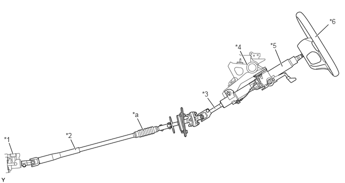
| *1 | Power Steering Gear Assembly | *2 | No .2 Steering Intermediate Shaft Sub-assembly |
| *3 | Steering Main Shaft Assembly | *4 | Instrument Panel Reinforcement |
| *5 | Steering Column Assembly | *6 | Steering Wheel Assembly |
| *a | Corrugated Shaft Section | - | - |
Secondary Collision
When an impact is transmitted to the steering wheel assembly during a collision (secondary collision), the break away bracket, which is secured to the instrument panel reinforcement through the break away capsule, detaches and moves forward. At this time, the sliding resistance between the steering column upper tube and steering column lower tube contributes to the reduction of impact energy while ensuring a survival space for the driver.
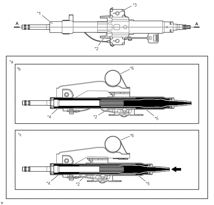
| *1 | Steering Column Assembly | *2 | Break Away Bracket |
| *3 | Break Away Capsule | *4 | Steering Column Lower Tube |
| *5 | Steering Column Upper Tube | *6 | Instrument Panel Reinforcement |
| *a | A- A Cross Section | *b | Before Collision |
| *c | After Collision | - | - |

|
Collision | - | - |