Home › Drivetrain › AXLE AND DIFFERENTIAL › AXLE SYSTEM
NM25T0E _52 Drivetrain _031390 AXLE AND DIFFERENTIAL _0141540 AXLE SYSTEM DE DETAILS F

AXLE AND DIFFERENTIAL  AXLE SYSTEM  DETAILS  DUAL MODE AUTOMATIC LOCKING HUB  


CONSTRUCTION


a.

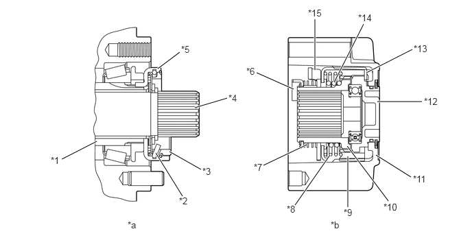
The dual mode automatic locking hub consists of a slide gear, drive gear, shift spring, return spring, retainer, knob, cam spring, cam, outer brake, inner brake, brake wire, release plate and housing.

i.

The drive force of the drive shaft is transmitted to the housing due to the engagement of the slide gear and drive gear.


ii.

The slide gear slides to engage the drive gear due to the operation of the knob, retainer, return spring and shift spring.


iii.

The cam rotates due to the operation of the outer brake, inner brake, brake wire and release plate.
X124102C01
0.938,2.417 1.469,2.146 true 2.396,1.042 2.729,0.792 true 2.958,1.635 3.448,1.49 true 2.573,2.302 3.052,2.573 true 2.365,2.323 2.771,2.979 true 3.896,1.104 4.458,1.354 true 4,2.51 4.656,2.198 true 4.479,3.115 5.01,2.354 true 5.281,3.146 5.281,2.375 true 5.896,3.052 5.271,2.219 true 6.24,2.688 5.708,2.354 true 6.406,1.542 5.729,1.542 true 6.26,0.75 5.563,1.104 true 5.521,0.365 5.073,1.25 true 4.781,0.292 4.781,1.063 true 0.771,2.354 1.083,2.51 0.313,0.156 10 false *1 2.719,2.969 3.031,3.125 0.313,0.156 10 false *2 3.073,2.521 3.385,2.677 0.313,0.156 10 false *3 3.469,1.406 3.781,1.563 0.313,0.156 10 false *4 2.75,0.667 3.063,0.823 0.313,0.156 10 false *5 3.74,1 4.052,1.156 0.313,0.156 10 false *6 3.854,2.458 4.167,2.615 0.313,0.156 10 false *7 4.354,3.094 4.667,3.25 0.313,0.156 10 false *8 5.219,3.146 5.531,3.302 0.313,0.156 10 false *9 5.823,3.063 6.292,3.219 0.469,0.156 10 false *10 6.271,2.635 6.74,2.792 0.469,0.156 10 false *11 6.438,1.458 6.906,1.615 0.469,0.156 10 false *12 6.281,0.656 6.75,0.813 0.469,0.156 10 false *13 5.438,0.188 5.906,0.344 0.469,0.156 10 false *14 4.677,0.115 5.146,0.271 0.469,0.156 10 false *15 1.938,3.333 2.25,3.49 0.313,0.156 10 false *a 5.021,3.333 5.333,3.49 0.313,0.156 10 false *b
*1 Spindle *2 Brake Wire
*3 Inner Brake *4 Drive Shaft
*5 Outer Brake *6 Release Plate
*7 Cam Spring *8 Shift Spring
*9 Slide Gear *10 Drive Gear
*11 Housing *12 Knob
*13 Retainer *14 Return Spring
*15 Cam - -
*a Axle Portion *b Housing Portion


X124103C01
0.813,1.906 1.177,1.677 true 2.135,1.115 3.063,0.521 true 0.656,1.854 0.969,2.01 0.313,0.156 10 false *1 3.094,0.396 3.406,0.552 0.313,0.156 10 false *2 1.938,2.427 2.25,2.583 0.313,0.156 10 false *a 5.115,2.417 5.427,2.573 0.313,0.156 10 false *b
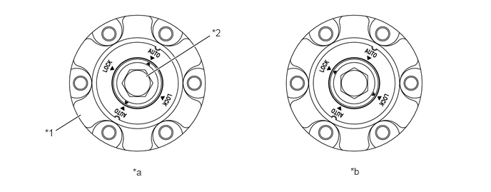
*1 Housing *2 Knob
*a AUTO Position *b LOCK Position


OPERATION


a.

AUTO Position

i.

Free→Lock Operation

·

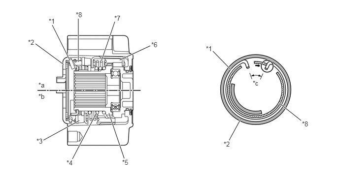
When switching the drive mode from H2 to H4 or L4, the drive gear and cam rotate due to the rotation of the drive shaft.

·

The outer brake is secured to the spindle. The cam moves the cam face of the outer brake while compressing the return spring.

·

The slide gear engages with the spline of the drive gear due to the movement of the cam. At this time, the inner brake is pressed into the cam and rotates. However, when the lug position of the inner brake contacts the inside of the brake wire opening, the brake operates due to the brake wire diameter expanding and contacting the inner surface of the outer brake and the rotation of the inner brake stops.
X124104C01
1.656,1.313 1.656,0.396 true 1.479,1.281 1.104,0.531 true 1.344,1.365 0.75,0.927 true 1.677,2.552 0.917,2.969 true 2.042,2.385 1.531,3.365 true 2.302,2.396 2.625,3.354 true 2.531,1.271 3.177,0.969 true 2.146,1.281 2.427,0.458 true 4.885,1.479 4.5,1.083 true 5.083,2.531 4.844,2.969 true 5.906,2.188 6.365,2.552 true 1.031,0.365 1.344,0.521 0.313,0.156 10 false *1 0.594,0.813 0.906,0.969 0.313,0.156 10 false *2 0.771,2.906 1.083,3.063 0.313,0.156 10 false *3 1.406,3.365 1.719,3.521 0.313,0.156 10 false *4 2.583,3.354 2.896,3.51 0.313,0.156 10 false *5 3.198,0.865 3.51,1.021 0.313,0.156 10 false *6 2.417,0.302 2.729,0.458 0.313,0.156 10 false *7 1.604,0.229 1.917,0.385 0.313,0.156 10 false *8 0.813,1.719 1.125,1.875 0.313,0.156 10 false *a 0.813,1.958 1.125,2.115 0.313,0.156 10 false *b 5.344,1.677 5.656,1.833 0.313,0.156 10 false *c 4.354,0.948 4.667,1.104 0.313,0.156 10 false *1 4.729,2.969 5.042,3.125 0.313,0.156 10 false *2 6.385,2.542 6.698,2.698 0.313,0.156 10 false *8
*1 Brake Wire *2 Outer Brake
*3 Cam *4 Return Spring
*5 Drive Gear *6 Slide Gear
*7 Shift Spring *8 Inner Brake
*a Lock Condition *b Free Condition
*c Expanded - -


·

When the inner brake stops rotating, the cam moves the cam face of the inner brake.

·

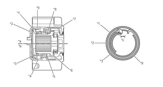
When the cam moves the cam face of the inner brake to the top position, the release plate, which is rotating in the same direction as the cam, contacts the outside of the brake wire opening and cancels the brake operation. Simultaneously, the brake wire is pressed into the release plate and rotates with the cam.

·

The cam holds the cam face of the inner brake at the top position and keeps the drive gear and slide gear engaged.
X124105C01
1.479,1.292 0.885,0.625 true 1.344,1.396 0.594,1.063 true 1.51,2.417 0.75,2.771 true 1.688,2.563 1.385,3.281 true 2.042,2.375 2.354,3.271 true 2.313,2.396 3.042,3.031 true 2.531,1.271 3.188,0.865 true 2.135,1.281 2.375,0.49 true 1.646,1.313 1.646,0.427 true 4.417,1.083 4.885,1.469 true 4.156,1.885 4.667,1.885 true 4.531,2.625 5.031,2.229 true 6.146,2.708 5.781,2.323 true 0.74,0.479 1.052,0.635 0.313,0.156 10 false *1 0.438,0.958 0.75,1.115 0.313,0.156 10 false *2 0.594,2.708 0.906,2.865 0.313,0.156 10 false *3 1.25,3.25 1.563,3.406 0.313,0.156 10 false *4 2.302,3.271 2.615,3.427 0.313,0.156 10 false *5 3.063,3 3.375,3.156 0.313,0.156 10 false *6 3.208,0.75 3.521,0.906 0.313,0.156 10 false *7 2.354,0.323 2.667,0.479 0.313,0.156 10 false *8 1.604,0.26 1.917,0.417 0.313,0.156 10 false *9 0.802,1.719 1.115,1.875 0.313,0.156 10 false *a 0.813,1.938 1.125,2.094 0.313,0.156 10 false *b 5.333,1.667 5.646,1.823 0.313,0.156 10 false *c 4.26,0.948 4.573,1.104 0.313,0.156 10 false *1 4,1.792 4.313,1.948 0.313,0.156 10 false *2 4.396,2.594 4.708,2.75 0.313,0.156 10 false *3 6.167,2.688 6.479,2.844 0.313,0.156 10 false *9
*1 Brake Wire *2 Outer Brake
*3 Release Plate *4 Cam
*5 Return Spring *6 Drive Gear
*7 Slide Gear *8 Shift Spring
*9 Inner Brake - -
*a Lock Condition *b Free Condition
*c Contracted - -


ii.

Lock→Free Operation

·

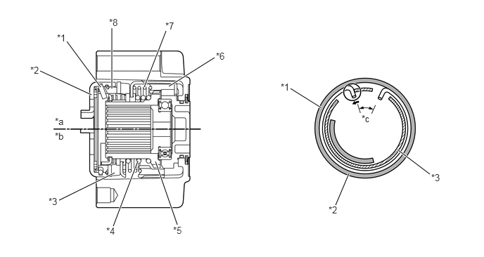
When the vehicle is driven in 4WD (either forward or in reverse) and the drive mode is switched from H4 or L4 to H2, and then the vehicle is driven in the opposite direction, the lug portion of the inner brake contacts the inside of the brake wire opening and the brake operates to stop the rotation of the inner brake.

·

The cam moves the cam face of the inner brake and outer brake.

·

The slide gear moves due to the force of the return spring and disengages from the drive gear, allowing the hub to become free.
X124106C01
1.49,1.292 0.99,0.615 true 1.354,1.406 0.594,1.052 true 1.698,2.563 0.875,2.969 true 2.042,2.385 1.677,3.354 true 2.302,2.396 2.625,3.333 true 2.5,1.281 3.177,0.854 true 2.135,1.292 2.458,0.458 true 1.656,1.313 1.656,0.417 true 4.302,1.313 4.75,1.594 true 4.969,3.042 5.167,2.573 true 6.365,2.583 5.885,2.219 true 0.844,0.479 1.156,0.635 0.313,0.156 10 false *1 0.448,0.958 0.76,1.115 0.313,0.156 10 false *2 0.719,2.906 1.031,3.063 0.313,0.156 10 false *3 1.573,3.344 1.885,3.5 0.313,0.156 10 false *4 2.563,3.333 2.875,3.49 0.313,0.156 10 false *5 3.198,0.75 3.51,0.906 0.313,0.156 10 false *6 2.448,0.302 2.76,0.458 0.313,0.156 10 false *7 1.615,0.25 1.927,0.406 0.313,0.156 10 false *8 0.813,1.719 1.125,1.875 0.313,0.156 10 false *a 0.813,1.938 1.125,2.094 0.313,0.156 10 false *b 5.354,1.677 5.667,1.833 0.313,0.156 10 false *c 4.156,1.208 4.469,1.365 0.313,0.156 10 false *1 4.865,3.031 5.177,3.188 0.313,0.156 10 false *2 6.385,2.552 6.698,2.708 0.313,0.156 10 false *3
*1 Brake Wire *2 Outer Brake
*3 Cam *4 Return Spring
*5 Drive Gear *6 Slide Gear
*7 Shift Spring *8 Inner Brake
*a Lock Condition *b Free Condition
*c Expanded - -


b.

LOCK Position

i.

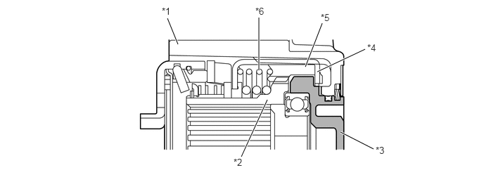
The cam face of the knob moves the slide gear through the retainer and shift spring.


ii.

The slide gear and drive gear are always engaged and the drive force of the drive shaft is transmitted to the wheels.
X124107C01
2.635,0.656 2.479,0.271 true 3.833,1.042 3.833,0.26 true 4.521,0.99 4.771,0.344 true 4.698,1.063 5.406,0.729 true 5.042,1.958 5.531,2.208 true 3.958,1.479 3.573,2.323 true 2.396,0.083 2.708,0.24 0.313,0.156 10 false *1 3.458,2.323 3.771,2.479 0.313,0.156 10 false *2 5.563,2.146 5.875,2.302 0.313,0.156 10 false *3 5.438,0.625 5.75,0.781 0.313,0.156 10 false *4 4.75,0.177 5.063,0.333 0.313,0.156 10 false *5 3.781,0.083 4.094,0.24 0.313,0.156 10 false *6
*1 Housing *2 Drive Gear
*3 Knob *4 Retainer
*5 Slide Gear *6 Shift Spring