Home › Engine / Hybrid System › 1VD-FTV FUEL › FUEL SYSTEM › from 2016.08
NM25T0E _51 Engine / Hybrid System _029307 1VD-FTV FUEL _0133907 FUEL SYSTEM DE DETAILS F

1VD-FTV FUEL  FUEL SYSTEM  DETAILS  SUPPLY PUMP  


CONSTRUCTION


a.

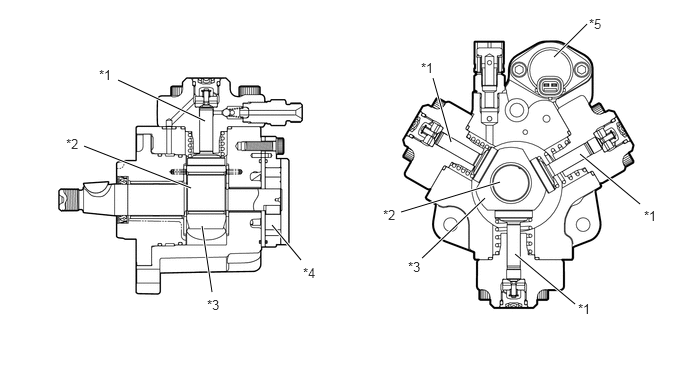
The supply pump assembly consists of an inner cam (eccentric cam), outer cam (polygon ring), 3 plungers, Suction Control Valve (SCV), and feed pump. Each plunger is placed outside of the outer cam.

i.

Feed pump pumps fuel to 3 plungers.


ii.

SCV controls volume of fuel drawn into plungers.


iii.

Inner cam drives outer cam.


iv.

Outer cam drives 3 plungers.


v.

Plunger pressurizes fuel.


b.

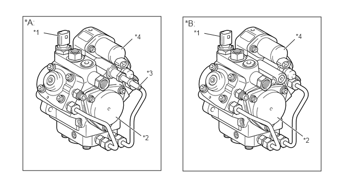
A fuel feeding pipe is provided on the supply pump assembly to supply fuel to the exhaust fuel addition injector assembly. The function, structure and operation are the same as those of the conventional supply pump assembly.*

*: Models compliant with EURO 5 emission regulations

W133121C01
0.479,0.344 3.375,3.573 2.896,3.229 3.833,0.354 6.729,3.583 2.896,3.229 0.917,0.688 1.24,0.75 true 2.427,2.448 2.958,2.844 true 2.917,1.802 3.094,1.615 true 2.542,1.031 2.771,0.813 true 4.281,0.698 4.604,0.76 true 5.813,2.458 6.344,2.854 true 5.948,1.042 6.177,0.823 true 0.51,0.365 0.823,0.542 0.313,0.177 12 false *A: 3.875,0.385 4.24,0.594 0.365,0.208 12 false *B: 0.698,0.594 0.917,0.823 0.219,0.229 10 false *1 2.99,2.802 3.302,2.958 0.313,0.156 10 false *2 3.073,1.448 3.385,1.604 0.313,0.156 10 false *3 2.823,0.688 3.135,0.844 0.313,0.156 10 false *4 4.063,0.604 4.281,0.833 0.219,0.229 10 false *1 6.354,2.854 6.667,3.01 0.313,0.156 10 false *2 6.198,0.677 6.51,0.833 0.313,0.156 10 false *4
*A Models Compliant with EURO 5 Emission Regulations *B Except Models Compliant with EURO 5 Emission Regulations
*1 Fuel Temperature Sensor *2 Feed Pump
*3 Fuel Feeding Pipe *4 SCV


Supply Pump Assembly Cross Section
W133122C01
1.229,0.833 2.135,1.26 true 0.875,1.521 1.99,1.958 true 5.771,0.594 6.115,0.25 true 3.135,2.708 2.833,2.344 true 2.208,3.042 2.104,2.354 true 4.396,2.688 5.052,2.063 true 4.177,2.208 5.208,1.896 true 4.51,0.813 4.698,1.479 true 5.365,2.646 5.99,3.167 true 6.042,1.604 6.667,2.125 true 4.385,0.625 4.698,0.781 0.313,0.156 10 false *1 0.688,1.417 1,1.573 0.313,0.156 10 false *2 4.25,2.698 4.563,2.854 0.313,0.156 10 false *3 3.156,2.76 3.469,2.917 0.313,0.156 10 false *4 2.156,3.094 2.469,3.25 0.313,0.156 10 false *3 3.99,2.156 4.302,2.313 0.313,0.156 10 false *2 6.021,3.135 6.333,3.292 0.313,0.156 10 false *1 6.708,2.167 7.021,2.323 0.313,0.156 10 false *1 1.031,0.698 1.344,0.854 0.313,0.156 10 false *1 6.135,0.167 6.448,0.323 0.313,0.156 10 false *5
*1 Plunger *2 Inner Cam
*3 Outer Cam *4 Feed Pump
*5 SCV -


OPERATION


a.

General

i.

The SCV controls the volume of fuel that is drawn into the plungers.


ii.

The ECM controls the opening of the Suction Control Valve (SCV) in order to regulate the volume of fuel that is pumped by the supply pump assembly to the common-rail assembly. Consequently, the fuel pressure in the common-rail assembly is controlled to the target injection pressure.


iii.

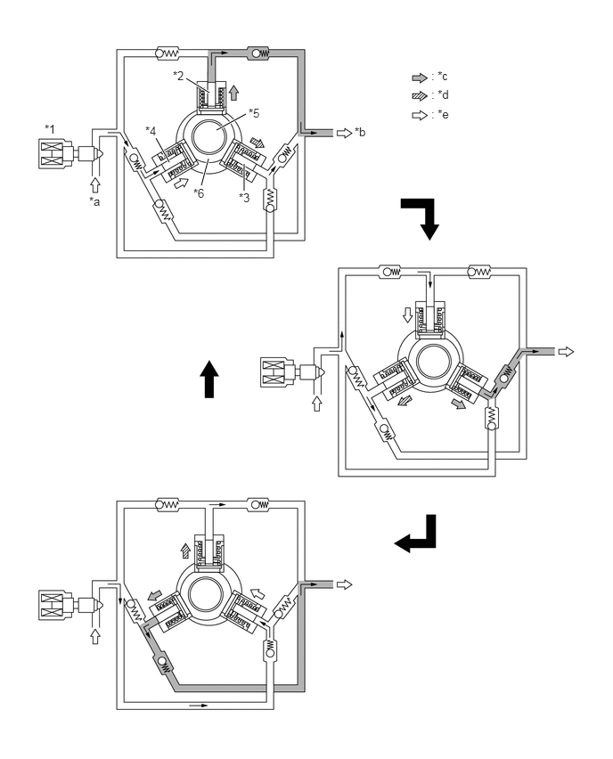
Due to the rotation of the inner cam (eccentric cam), the outer cam pushes plunger "A" upward as illustrated below. The force of the spring pulls plungers "B" and "C". As a result, plungers "B" and "C" draw fuel in, and plunger "A" pumps fuel at the same time.
W123241C01
2.177,0.917 2.448,1.083 true 1.823,1.615 1.979,1.896 true 2.438,1.854 2.354,2.167 true 2.854,1.917 2.854,2.229 true 2.531,1.521 2.875,1.333 true 0.521,1.427 0.833,1.583 0.313,0.156 10 false *1 2.021,0.802 2.333,0.958 0.313,0.156 10 false *2 2.792,2.229 3.104,2.385 0.313,0.156 10 false *3 1.698,1.448 2.01,1.604 0.313,0.156 10 false *4 2.906,1.24 3.219,1.396 0.313,0.156 10 false *5 2.26,2.177 2.573,2.333 0.313,0.156 10 false *6 1.042,2.271 1.354,2.427 0.313,0.156 10 false *a 4.146,1.458 4.458,1.615 0.313,0.156 10 false *b 5.042,0.802 5.354,0.958 0.313,0.156 10 false : *c 5.042,1.021 5.354,1.177 0.313,0.156 10 false : *d 5.042,1.25 5.354,1.406 0.313,0.156 10 false : *e
*1 SCV *2 Plunger "A"
*3 Plunger "B" *4 Plunger "C"
*5 Inner Cam *6 Outer Cam
*a Suction *b To Injector
*c Pumping Finish *d Pumping Start
*e Suction - -


b.

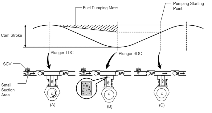
SCV Opening Small

W133162E02
2.542,0.875 2.542,0.26 2.542,0.26 2.771,0.26 true 5.427,0.75 5.594,0.104 5.594,0.104 5.771,0.104 true 0.896,2.354 0.688,2.146 0.688,2.146 0.448,2.146 true 0.948,2.531 0.875,2.813 0.875,2.813 0.594,2.813 true 0.031,1.104 0.813,1.448 0.781,0.344 10 false Cam Stroke 1.708,1.688 2.563,2.031 0.854,0.344 10 false Plunger TDC 2.802,0.177 4.177,0.51 1.375,0.333 10 false Fuel Pumping Mass 4.01,1.719 4.865,2.063 0.854,0.344 10 false Plunger BDC 5.854,0.031 7.042,0.646 1.188,0.615 10 false Pumping Starting Point 0.104,2.073 0.51,2.375 0.406,0.302 10 false SCV 0.042,2.781 0.604,3.708 0.563,0.927 10 false Small Suction Area 1.688,3.448 1.958,3.729 0.271,0.281 10 false (A) 3.615,3.5 3.885,3.781 0.271,0.281 10 false (B) 5.375,3.458 5.646,3.74 0.271,0.281 10 false (C)

(A) When the opening of the SCV is small, the fuel suction area is kept small, which decrease the transferable fuel quantity.
(B) The plunger strokes fully, however, the suction volume becomes small due to the small suction area. Therefore, the difference of the volume between the geometry volume and the suction volume is in vacuum condition.
(C) Pumping will start at the time when the fuel pressure has become higher than the common-rail assembly pressure.


c.

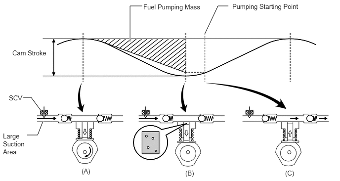
SCV Opening Large

W133163E02
2.74,0.875 2.74,0.125 2.74,0.125 3,0.125 true 4.313,0.719 4.594,0.125 4.594,0.125 4.813,0.125 true 0.865,2.333 0.656,2.052 0.656,2.052 0.49,2.052 true 0.906,2.552 0.792,2.844 0.792,2.844 0.573,2.844 true 0.26,1.031 1.031,1.427 0.771,0.396 10 false Cam Stroke 3.021,0.063 4.396,0.542 1.375,0.479 10 false Fuel Pumping Mass 4.896,0.052 6.74,0.438 1.844,0.385 10 false Pumping Starting Point 0.188,1.979 0.615,2.271 0.427,0.292 10 false SCV 0.063,2.781 0.594,3.75 0.531,0.969 10 false Large Suction Area 1.719,3.521 2.177,3.719 0.458,0.198 10 false (A) 3.906,3.563 4.365,3.76 0.458,0.198 10 false (B) 6.01,3.563 6.469,3.76 0.458,0.198 10 false (C)

(A) When the opening of the SCV is large, the fuel suction area is kept large, which increase the transferable fuel quantity.
(B) If the plunger strokes fully, the suction volume will increase because the suction area is large.
(C) Pumping will start at the time when the fuel pressure has become higher than the common-rail assembly pressure.