1VD-FTV FUEL FUEL SYSTEM DETAILS INJECTOR
CONSTRUCTION
Models Compliant with EURO 4 Emission Regulations
An injector assembly consists of a nozzle needle, piston, and solenoid valve.
An injector compensation value and Quick Response (QR) code containing encoded characteristics of the injector assembly are printed on each injector.
The injector compensation value and QR code contain various pieces of information regarding the injector assembly, such as model code, injection volume correction, and injection timing correction values.
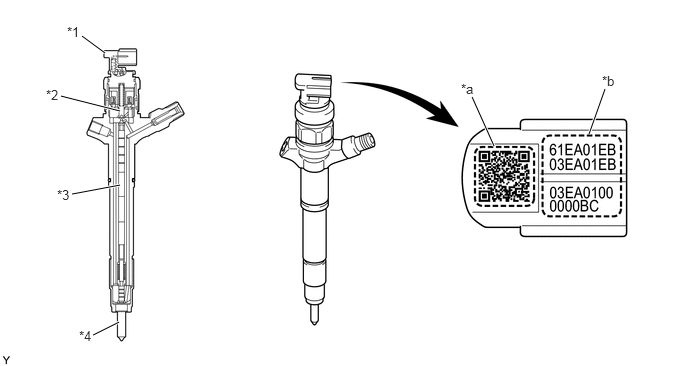
| *1 | Injector Assembly | *2 | Solenoid Valve |
| *3 | Piston | *4 | Nozzle Needle |
| *a | QR Code | *b | Injector Compensation Value |
- HINT:
-
·
If the ECM is replaced, use the Global TechStream (GTS) and input the injector compensation values of all 8 injector assemblies. If one of the injector assemblies is replaced, input the injector compensation value of the replaced injector assembly. Then, the proper compensation will be made so that the injection volume precision prior to the replacement will remain unchanged. For details, refer to the Repair Manual.
·The QR code, which requires a special scan tool, is not used at TOYOTA dealers.
·What is QR (Quick Response) Code?
-QR code, a matrix symbology consisting of an array of nominally square cells, allows omni-directional, high-speed reading of large amounts of data.
-QR code encodes many types of data such as numeric, alphanumeric, kanji, kana and binary code. A maximum of 7,089 characters (numeric) can be encoded.
-QR code (2D code) contains information in the vertical and horizontal directions, whereas a bar code contains data in one direction only. QR code (2D code) holds a considerably greater volume of information than a bar code.
Models Compliant with EURO 5 Emission Regulations
8 piezo type injector assemblies are used. Each injector assembly consists of a nozzle needle, 2 pistons, a three-way valve and a piezo actuator.
An injector compensation value and QR (Quick Response) code containing encoded characteristics of the injector assembly are printed on each injector assembly.
The injector compensation value and QR code contain various pieces of information regarding the injector assembly, such as model code, injection volume correction and injection timing correction values.
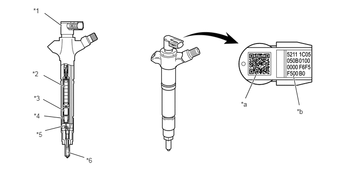
| *1 | Injector Assembly | *2 | Piezo Actuator |
| *3 | No. 1 Piston | *4 | No. 2 Piston |
| *5 | Three-way Valve | *6 | Nozzle Needle |
| *a | QR Code | *b | Injector Compensation Value |
- HINT:
-
·
If the ECM is replaced, use the Global TechStream (GTS) and input the injector compensation values of all 8 injector assemblies. If one of the injector assemblies is replaced, input the injector compensation value of the replaced injector assembly. Then, the proper compensation will be made so that the injection volume precision prior to the replacement will remain unchanged. For details, refer to the Repair Manual.
·The QR code, which requires a special scan tool, is not used at TOYOTA dealers.
·What is Quick Response (QR) Code?:
-QR code, a matrix symbology consisting of an array of nominally square cells, allows omni-directional, high-speed reading of large amounts of data.
-QR code encodes many types of data such as numeric, alphanumeric, kanji, kana and binary code. A maximum of 7,089 characters (numeric) can be encoded.
-QR code (2D code) contains information in the vertical and horizontal directions, whereas a bar code contains data in one direction only. QR code (2D code) holds a considerably greater volume of information than a bar code.
OPERATION
Models Compliant with EURO 4 Emission Regulations
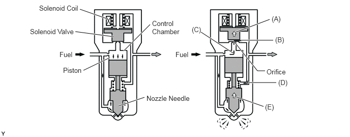
| (A) | When electrical current is applied to the solenoid coil, it pulls the solenoid valve up. |
| (B) | The orifice of the control chamber opens, allowing the fuel to flow out. |
| (C) | The fuel pressure in the control chamber drops. |
| (D) | Simultaneously, fuel flows from the orifice to the bottom of the piston and raises the piston up (to enhance response). |
| (E) | As a result, the piston raises the nozzle needle to inject fuel. |
Models Compliant with EURO 5 Emission Regulations
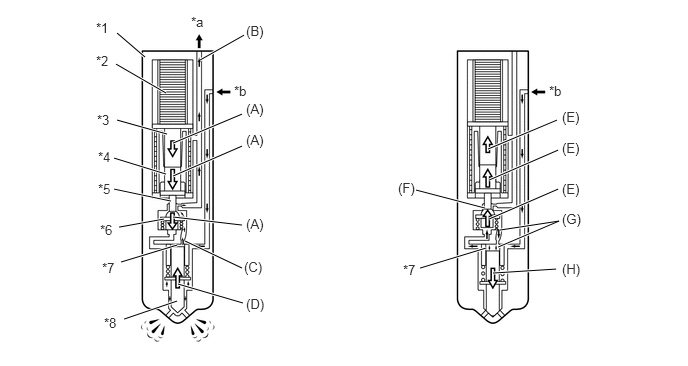
| *1 | Injector Assembly | *2 | Piezo Actuator |
| *3 | No. 1 Piston | *4 | No. 2 Piston |
| *5 | Orifice | *6 | Three-way Valve |
| *7 | Control Chamber | *8 | Nozzle Needle |
| *a | Return Fuel | *b | Fuel from Common-rail assembly |
| (A) | When current is applied to the piezo actuator, the No. 1 piston, No. 2 piston and three-way valve are pushed down. |
| (B) | The orifice on the upper part of the three-way valve opens and the fuel in the control chamber flows out. |
| (C) | The fuel pressure in the control chamber drops. |
| (D) | As a result, the nozzle needle is pushed up due to fuel pressure, causing fuel injection. |
| (E) | Negative current is applied the piezo actuator, the No. 1 and No. 2 pistons and the three-way valve are pushed up. |
| (F) | The orifice on the upper part of the three-way valve closes to stop fuel flow. |
| (G) | The fuel pressure in the control chamber rises. |
| (H) | As a result, the nozzle needle goes down to stop fuel injection. |