1VD-FTV EMISSION CONTROL EMISSION CONTROL SYSTEM CONTROL CATALYST SUPPORT CONTROL
SYSTEM CONTROL
In order to regenerate the DPF, the temperature of the DPF is increased to combust the accumulated PM in the DPF, expelling it as CO2 and H2O.
The ECM monitors the engine condition and calculates the total amount of accumulated PM. In addition, the ECM calculates the amount of combusted PM according to the engine speed, fuel injection volume and the injection volume of the exhaust fuel addition injector assembly. The amount of accumulated PM in the DPF is calculated based on the calculated total amount of accumulated PM and the amount of combusted PM. The ECM urges the driver to perform PM automatic or manual regeneration according to the level of accumulated PM.
When automatic or manual regeneration is performed, the injection of the exhaust fuel addition injector assembly and the engine combustion condition are controlled, increasing the temperature of the DPF. As a result, the temperature of the DPF becomes approximately 600°C to 700°C and PM is combusted.
When the vehicle is continuously driven with a high exhaust temperature such as at high speeds, the temperature of the DPF is sufficiently increased and PM is spontaneously combusted. At this time, no special control such as exhaust fuel addition injector assembly control, etc. is performed.
When the vehicle is continuously driven while the temperature of the DPF is not high enough for PM combustion such as when driving for a short distance or driving for a short time, catalyst performance is decreased. As a result, PM is accumulated in the DPF. When the amount of accumulated PM exceeds the threshold (for automatic regeneration), the ECM performs automatic regeneration until the amount of PM reaches zero.
If the vehicle continues to be driven for a short distance even after automatic regeneration is performed, more PM is accumulated. When the amount of accumulated PM exceeds the threshold (for manual regeneration), the DPF warning light illuminates or blinks to urge the driver to perform manual regeneration.
Automatic Regeneration
When automatic regeneration is being performed, the ECM controls the fuel injection of the exhaust fuel addition injector assembly and the engine combustion condition, increasing the temperature of the DPF to combust the PM. Idle up is performed while the vehicle is stopped.
- HINT:
-
The end of automatic regeneration is calculated by the ECM according to the amount of accumulated PM.
Manual Regeneration
The following methods are used to perform manual regeneration. For details of manual regeneration operation, refer to the Repair Manual.
DPF Switch Operation Method
Stop the vehicle and press the DPF switch to perform manual regeneration.
- HINT:
-
Operating the clutch pedal or accelerator pedal while regeneration is being performed temporarily stops regeneration.
Global TechStream (GTS) Operation Method
Stop the vehicle and operate the Global TechStream (GTS) to perform manual regeneration.
When manual regeneration is being performed, the ECM controls the fuel injection of the exhaust fuel addition injector assembly and the engine combustion condition and performs idle up, increasing the temperature of the DPF to combust the PM.
- HINT:
-
The end of manual regeneration is calculated by the ECM according to the amount of accumulated PM.
Fail-safe
If manual regeneration is performed when the amount of accumulated PM is beyond the threshold, the DPF may get damaged. Therefore, when the amount of accumulated PM exceeds the threshold (for the fail-safe function), the injection volume is controlled to a minimum level to cancel regeneration control. As a result, manual regeneration cannot be performed properly. At the same time, the MIL illuminates and the DPF warning light blinks to notify the driver of a malfunction.
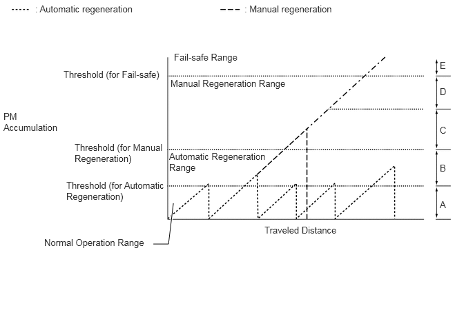
| Text in Illustration | DPF Indicator Display | MIL | DPF Warning Light |
|---|---|---|---|
| A | 0 to 3 | - | - |
| B | 4 to 6 | - | - |
| C | 7 to 8 | - | Illuminate |
| D | 9 | - | Blink |
| E | 10 | Illuminate | Blink |
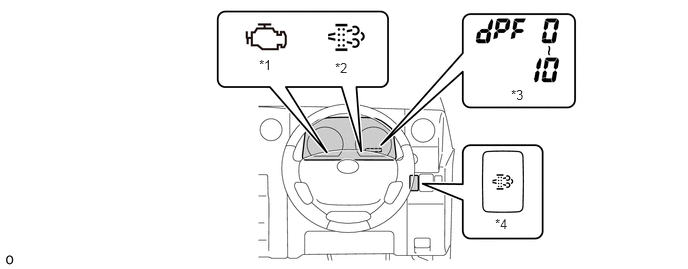
| *1 | MIL | *2 | DPF Warning Light |
| *3 | DPF Indicator (Displayed on Odometer/trip Meter) | *4 | DPF Switch |