Home › Suspension › FRONT SUSPENSION › FRONT SUSPENSION SYSTEM › from 2016.08
NM25T0E _53 Suspension _031102 FRONT SUSPENSION _0140237 FRONT SUSPENSION SYSTEM DE DETAILS F

FRONT SUSPENSION  FRONT SUSPENSION SYSTEM  DETAILS  SUSPENSION ARM  


CONSTRUCTION


a.

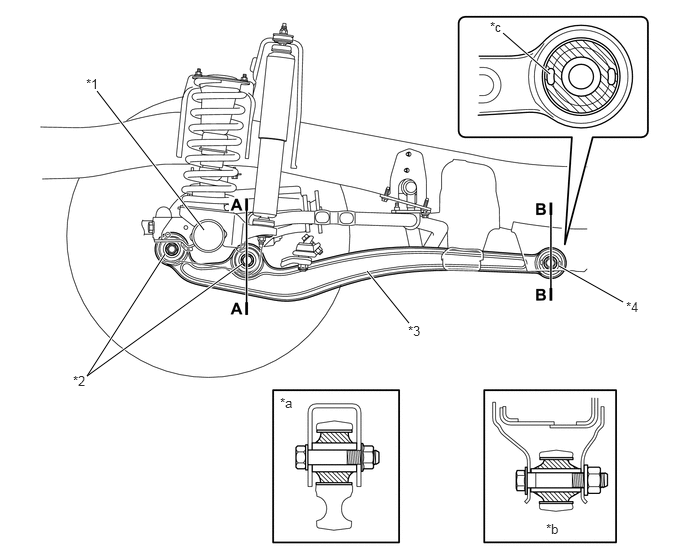
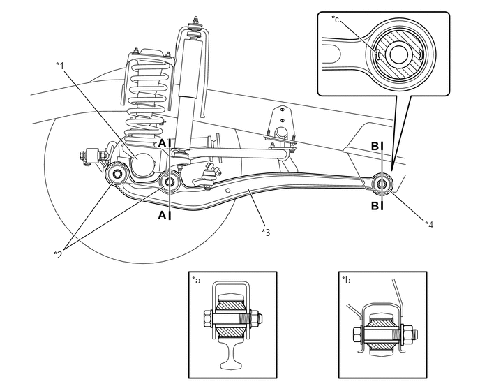
A forged leading arm is used to strengthen the durability aspect of the 4WD vehicle.


b.

An inter-ring bush with axial drillings is used for the lower arm bush on the frame side of the leading arm to ensure a full suspension stroke and improve drive performance on rough roads and riding comfort. Also, the inter-ring bush used for the control arm bush on the front axle housing side is optimally positioned so that when the vehicle rolls, an even larger roll stiffness is achieved using the bush reaction force.


c.

The span of the leading arm is lengthened and the frame side installation area is positioned lower than the center of the axle. These 2 characteristics suppress axle steer generated when turning and generate axle steer in the direction opposite of the steering direction to create understeer.
Except Super Long Wheel Base Single Cab Pick-up Models for Australia
X132467C01
2.052,2.385 0.958,1.063 true 2.448,2.781 0.948,3.729 0.948,3.729 1.708,2.688 true 3.958,3.375 3.708,2.823 true 6.323,3.292 5.781,2.813 true 5.625,0.792 5.083,0.313 true 0.833,0.896 1.146,1.094 0.313,0.198 10 false *1 0.802,3.719 1.115,3.917 0.313,0.198 10 false *2 3.906,3.385 4.219,3.583 0.313,0.198 10 false *3 6.344,3.271 6.656,3.469 0.313,0.198 10 false *4 4.948,0.198 5.26,0.396 0.313,0.198 10 false *c 2.865,4.094 3.177,4.292 0.313,0.198 10 false *a 5.104,4.094 5.417,4.292 0.313,0.198 10 false *b
*1 Front Axle Housing *2 Control Arm Bush
*3 Front Leading Arm *4 Lower Arm Bush
*a A - A Cross Section *b B - B Cross Section
*c Axial Drillings - -


Super Long Wheel Base Single Cab Pick-up Models for Australia
X132468C01
2.125,2.396 1.01,0.948 true 2.521,2.75 0.906,3.917 0.906,3.917 1.719,2.646 true 4.26,3.365 3.823,2.823 true 6.49,3.146 5.823,2.771 true 5.729,0.771 5.24,0.344 true 0.896,0.792 1.208,0.99 0.313,0.198 10 false *1 0.76,3.885 1.073,4.083 0.313,0.198 10 false *2 4.25,3.365 4.563,3.563 0.313,0.198 10 false *3 6.521,3.115 6.833,3.313 0.313,0.198 10 false *4 2.917,4.115 3.229,4.313 0.313,0.198 10 false *a 5.688,5.427 6,5.625 0.313,0.198 10 false *b 5.104,0.198 5.417,0.396 0.313,0.198 10 false *c
*1 Front Axle Housing *2 Control Arm Bush
*3 Front Leading Arm *4 Lower Arm Bush
*a A - A Cross Section *b B - B Cross Section
*c Axial Drillings - -


d.

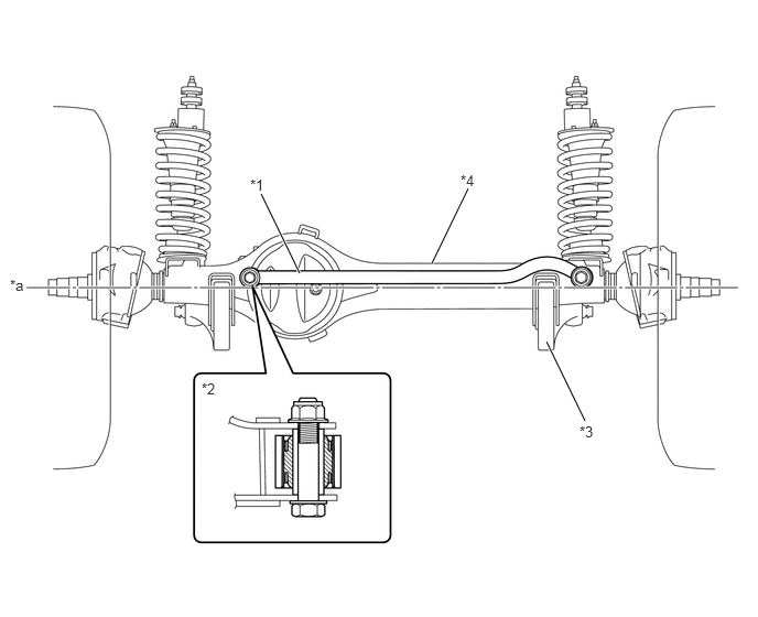
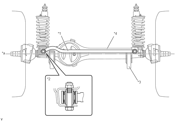
The lateral control rod has been made solid and round to ensure durability. Also, an inter-ring bush is used.


e.

The front axle housing side installation area of the lateral control rod is positioned higher than the center of the axle to heighten the roll center position.
Except Super Long Wheel Base Single Cab Pick-up Models for Australia
X124392C01
2.708,2.031 2.438,1.427 true 4.26,1.948 4.531,1.448 true 5.479,3.208 5.135,2.646 true 2.302,1.25 2.615,1.406 0.313,0.156 10 false *1 1.875,3.063 2.188,3.219 0.313,0.156 10 false *2 5.479,3.188 5.792,3.344 0.313,0.156 10 false *3 4.531,1.25 4.844,1.406 0.313,0.156 10 false *4 0.073,2.031 0.385,2.188 0.313,0.156 10 false *a
*1 Front Lateral Control Rod *2 Front Lateral Control Rod Bush Sub-assembly
*3 Front Leading Arm *4 Front Axle Housing
*a Center of Axle - -


Super Long Wheel Base Single Cab Pick-up Models for Australia
X132469C01
2.833,2.583 2.469,1.833 true 5.531,3.979 5.167,3.229 true 4.083,2.49 4.427,1.781 true 2.365,1.667 2.677,1.865 0.313,0.198 10 false *1 1.906,3.594 2.219,3.792 0.313,0.198 10 false *2 5.479,4 5.792,4.198 0.313,0.198 10 false *3 4.354,1.625 4.667,1.823 0.313,0.198 10 false *4 0.094,2.615 0.406,2.813 0.313,0.198 10 false *a
*1 Front Lateral Control Rod *2 Front Lateral Control Rod Bush Sub-assembly
*3 Front Leading Arm *4 Front Axle Housing
*a Center of Axle - -