NETWORKING MULTIPLEX COMMUNICATION SYSTEM GENERAL GENERAL
OUTLINE
The multiplex communication system uses the following communication protocol:
The Controller Area Network (CAN) is used for communication between the engine and chassis system.
HS-CAN (high speed) is used for the CAN.
The central gateway ECU is used as gateways to transmit data between the buses.*
*: Models with central gateway ECU
MAIN FEATURES
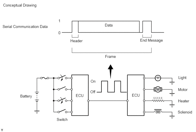
Multiplex communication uses serial communication data that consists of bits and frames in order to exchange information between the various ECUs. This allows a reduction of the amount of wiring used in the vehicle.
A bit is the basic unit of communication used to represent the information. A bit is represented by binary values of "0" or "1".
A frame is a body of data transmitted together. A frame contains a header that indicates the beginning, and an end message that indicates the end.
CAN Type
The CAN protocol is the rule for establishing data communication. If the ECUs in the network use different frameworks for their data, such as communication speed, communication wire, and signals, they will be unable to understand each other. Therefore, a protocol (rule) must be established among them.
The CAN is able to transmit larger amounts of data faster than other protocols. This feature makes it possible to transmit data accurately in the engine and chassis system, which requires large amounts of data to be transmitted in short periods of time.
| Protocol | CAN (ISO Standard) |
|---|---|
| Communication Speed | 500 kbps*/HS-CAN (High Speed) |
| Communication Wire | Twisted-pair Wire |
| Drive Type | Differential Voltage Drive |
| Data Length | 1-8 Bytes (Variable) |
- HINT:
-
*: bps is an abbreviation of "Bits Per Second", indicating the number of bits that can be transmitted per second.
Communication Wire
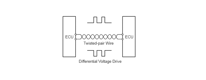
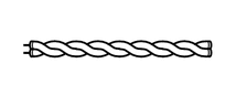
A twisted pair of wires is used for CAN communication.
| Communication Wire | Outline | |
|---|---|---|
| Twisted-pair Wire |
|
This communication wire is a pair of twisted wires. Communication is driven by applying different voltages to the 2 lines in order to send a single signal. This system, which is called a "Differential Voltage Drive", reduces noise. |