1VD-FTV ENGINE MECHANICAL CYLINDER HEAD REPLACEMENT
PROCEDURE

 11122 1.REPLACE VALVE GUIDE BUSH
Gradually heat the cylinder head sub-assembly to 80 to 100°C (176 to 212°F).
Place the cylinder head sub-assembly on a wooden block.
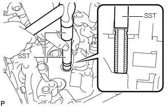
Using SST and a hammer, tap out the valve guide bush.
- SST
-
09201-10000 (09201-01060)
09950-70010 (09951-07100)
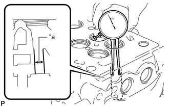
| *a | Bore Diameter |
Using a caliper gauge, measure the bush bore diameter of the cylinder head sub-assembly.
- Standard bush bore diameter:
-
10.985 to 11.006 mm (0.432 to 0.433 in.)
If the bush bore diameter of the cylinder head sub-assembly is more than 11.006 mm (0.433 in.), machine the bush bore to the dimension of 11.035 to 11.056 mm (0.434 to 0.435 in.).
- Standard Valve Guide Bush Diameter:
-
Item Specified Condition STD 11.033 to 11.044 mm (0.434 to 0.435 in.) O/S 0.05 11.083 to 11.094 mm (0.436 to 0.437 in.)
If the bush bore diameter of the cylinder head sub-assembly is more than 11.56 mm (0.435 in.), replace the cylinder head sub-assembly.
Gradually heat the cylinder head sub-assembly to 80 to 100°C (176 to 212°F).
Place the cylinder head sub-assembly on a wooden block.
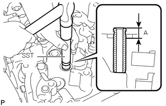
Using SST, tap in a new valve guide bush to the specified protrusion height labeled A shown in the illustration.
- SST
-
09201-10000 (09201-01060)
09950-70010 (09951-07100)
- Standard protrusion height:
-
9.0 to 9.4 mm (0.354 to 0.370 in.)
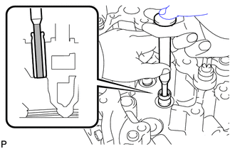
Using a sharp 6.0 mm reamer, ream the valve guide bush to obtain the standard specified clearance between the valve guide bush and valve stem.
- Standard Overall Length:
-
Item Specified Condition Intake 0.025 to 0.060 mm (0.000984 to 0.00236 in.) Exhaust 0.035 to 0.070 mm (0.00138 to 0.00276 in.)
11155A 2.REPLACE CYLINDER HEAD RING PIN
- HINT:
-
It is not necessary to remove the cylinder head ring pin unless it is being replaced.
Remove the cylinder head ring pin.
Using a plastic-faced hammer, tap in a new cylinder head ring pin until the pin stops.
- Standard protrusion:
-
4.4 to 5.6 mm (0.173 to 0.220 in.)
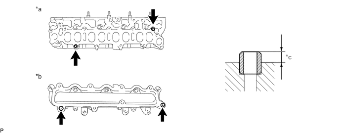
| *a | Cylinder Head Sub-assembly Side | *b | Intake Manifold Side |
| *c | 4.4 to 5.6 mm (0.173 to 0.220 in.) | - | - |