1HZ ENGINE MECHANICAL CYLINDER HEAD REASSEMBLY
PROCEDURE

 11165 1.SELECT COMBUSTION CHAMBER SHIM
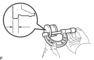
If using new combustion chamber sub-assembly:
Using a micrometer, measure the thickness of each used combustion chamber sub-assembly at the position shown in the illustration, then select the number of combustion chamber shims to be used.
- Select the Number of Combustion Chamber Shim:
-
Combustion chamber thickness No. of shims to be used 6.02 to 6.05 mm (0.2370 to 0.2382 in.) 0 6.06 to 6.08 mm (0.2386 to 0.2394 in.) 1 6.09 to 6.11 mm (0.2398 to 0.2406 in.) 2
- Combustion Chamber Shim thickness:
-
0.03 mm (0.00118 in.)
- NOTICE:
-
If combustion chamber shims were already being used, do not perform the above step, use the same number of combustion chamber shims as were used before.
If reusing combustion chamber sub-assembly:
Install the combustion chamber sub-assembly back in the same position it was originally at.
11106 2.INSTALL COMBUSTION CHAMBER SUB-ASSEMBLY
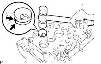
Align the knock pin of the combustion chamber sub-assembly with the notch of the cylinder head sub-assembly.
Using a plastic-faced hammer, tap in the combustion chamber sub-assembly.
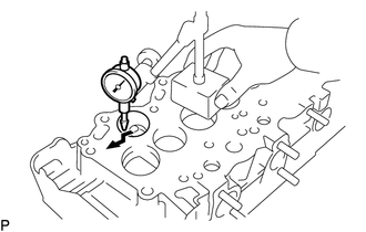
Using a dial indicator, measure the protrusion of the combustion chamber sub-assembly from the cylinder head sub-assembly.
- Combustion chamber protrusion:
-
Minus 0.04 to Plus 0.04 mm (Minus 0.00157 to Plus 0.00157 in.)
If the protrusion is less than the specified, adjust with combustion chamber shims.
- Combustion Chamber Shim thickness:
-
0.03 mm (0.00118 in.)
If the protrusion is more than the specified, replace the combustion chamber sub-assembly and recheck the protrusion.
3.INSTALL VALVES
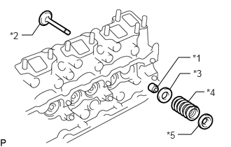
| *1 | Valve Stem Oil Seal |
| *2 | Valve |
| *3 | Valve Spring Seat Plate Washer |
| *4 | Compression Spring |
| *5 | Valve Spring Retainer |
Install the following parts:
Valve stem oil seal
Valve
Valve spring seat plate washer
Compression spring
Valve spring retainer
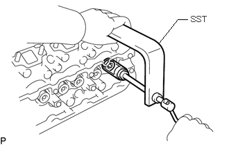
Using SST, compress the compression spring and place the 2 valve spring retainer locks around the valve stem.
- SST
-
09202-70020 (09202-00030, 09202-01010, 09202-01020)
Using a plastic-faced hammer, lightly tap the valve stem tip to ensure a proper fit.