RM25T0E _58 Vehicle Interior _029469 HEATING / AIR CONDITIONING _0133768 AIR CONDITIONING SYSTEM D
HEATING / AIR CONDITIONING AIR CONDITIONING SYSTEM SYSTEM DESCRIPTION
FUNCTION OF MAIN COMPONENTS
a.
The main components of the air conditioning system have the following functions:
| Component | Function |
|---|---|
|
*1: w/ Air Conditioning System *2: w/ Heater |
|
| Heater Blower Switch Assembly | Allows operation and adjustment of the air conditioning system via switches. |
| Cooler Stabilizer Amplifier Assembly | Transmits and receives signals to and from the switches and sensors. |
| Cooler Compressor Assembly*1 | A compact, lightweight, and low-noise 10-cylinder swash plate type cooler compressor is used. |
| Cooler Condenser Assembly*1 | A multi-flow sub-cool condenser is used to improve heat exchange efficiency. |
| Heater Radiator Assembly*2 | A multi-flow type heater radiator is used for compactness and high performance. |
| Blower with Motor Sub-assembly | The blower with fan motor sub-assembly is controlled by the blower switch on the heater blower switch assembly. |
| No. 1 Cooler Evaporator Sub-assembly*1 | A multi-flow type evaporator is used for compactness. |
| No. 1 Cooler Thermistor*1 | Detects the temperature of the cool air past the No. 1 cooler evaporator sub-assembly and transmits the data to the cooler stabilizer amplifier assembly. |
| ECM | Transmits the air conditioning off request signal to the cooler stabilizer amplifier assembly. |
MODE POSITION AND DAMPER OPERATION
a.
Mode Position and Damper Operation
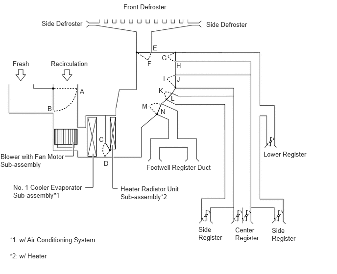
1.385,3.323 1.563,3.323 1.563,3.323 1.552,3.021 true 1.813,3.99 1.979,3.99 1.979,3.99 1.979,3.271 true 2.5,4.01 2.396,4.01 2.396,4.01 2.396,3.094 true 0.271,1.271 1.042,1.469 0.771,0.198 10 false Fresh 1.083,1.271 2.198,1.583 1.115,0.313 10 false Recirculation 1.698,1.865 1.927,2.094 0.229,0.229 10 false A 1.01,2.229 1.24,2.458 0.229,0.229 10 false B 0.01,3.25 1.406,3.792 1.396,0.542 10 false Blower with Fan Motor Sub-assembly 0.281,3.906 1.75,4.49 1.469,0.583 10 false No. 1 Cooler Evaporator Sub-assembly*1 2.563,3.938 3.813,4.479 1.25,0.542 10 false Heater Radiator Unit Sub-assembly*2 0.208,5.365 1.333,5.583 1.125,0.219 10 false *2: w/ Heater 2.625,0.063 4.021,0.604 1.396,0.542 10 false Front Defroster 3.25,0.938 3.479,1.167 0.229,0.229 10 false E 3.135,1.271 3.375,1.667 0.24,0.396 10 false F 3.438,1.146 3.667,1.375 0.229,0.229 10 false G 3.75,1.313 3.979,1.542 0.229,0.229 10 false H 3.469,1.594 3.698,1.823 0.229,0.229 10 false I 3.115,3.479 4.635,3.833 1.521,0.354 10 false Footwell Register Duct 5.604,3.198 7,3.74 1.396,0.542 10 false Lower Register 2.104,2.885 2.333,3.115 0.229,0.229 10 false C 2.208,3.396 2.438,3.625 0.229,0.229 10 false D 4.219,4.802 4.75,5.448 0.531,0.646 10 false Side Register 5,4.813 5.531,5.458 0.531,0.646 10 false Center Register 5.781,4.823 6.313,5.469 0.531,0.646 10 false Side Register 3.76,1.604 3.99,1.833 0.229,0.229 10 false J 3.375,1.844 3.604,2.073 0.229,0.229 10 false K 3.635,2.01 3.865,2.24 0.229,0.229 10 false L 3.021,2.177 3.25,2.406 0.229,0.229 10 false M 3.417,2.292 3.646,2.531 0.229,0.24 10 false N 0.208,5.021 2.427,5.24 2.219,0.219 10 false *1: w/ Air Conditioning System 4.385,0.438 5.781,0.979 1.396,0.542 10 false Side Defroster 0.885,0.417 2.281,0.958 1.396,0.542 10 false Side Defroster
| Control Damper | Operation Position | Damper Position | Operation | |
|---|---|---|---|---|
| Air Inlet Control Damper | Fresh | A | Brings in fresh air. | |
| Recirculation | B | Recirculates internal air. | ||
| Air Mix Control Damper | MAX COLD to MAX HOT | C - D | Varies the mixture ratio of cold air to hot air in order to regulate the temperature continuously from hot to cold. | |
| Mode Control Damper |

|
FACE | E, G, I, K, N | Air blows out of the center register, side register and the side defroster. In addition, air blows out slightly from the lower register duct. |

|
BI-LEVEL | E, G, I, K, M | Air blows out of the center register, side register and footwell register duct. In addition, air blows out slightly from the lower register duct. | |

|
FOOT | F, G, J, K, M | Air blows out of the front defroster, side register and footwell register duct. In addition, air blows out slightly from the side defroster and the lower register. | |

|
FOOT/DEF | F, G, I, K, M | Air blows out of the front defroster, side register and footwell register duct. In addition, air blows out slightly from the lower register, the side defroster and the center register. | |

|
DEF | F, G, I, K, N | Air blows out of the front defroster and side register. In addition, air blows out slightly from the side defroster, the center register and lower register duct. | |
AIR OUTLETS AND AIRFLOW VOLUME
a.
Air Outlets and Airflow Volume
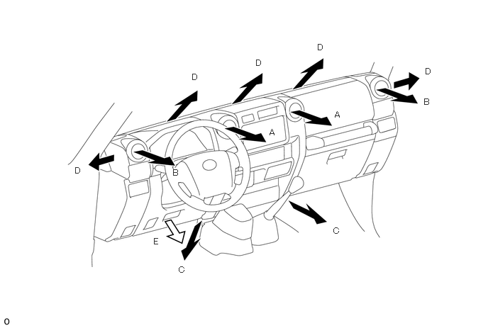
3.958,1.875 4.115,2.073 0.156,0.198 10 true A 4.917,1.615 5.073,1.813 0.156,0.198 10 true A 6.229,1.427 6.385,1.625 0.156,0.198 10 true B 2.542,2.469 2.698,2.667 0.156,0.198 10 true B 2.625,3.896 2.781,4.094 0.156,0.198 10 true C 4.896,3.323 5.052,3.521 0.156,0.198 10 true C 2.823,1.063 2.979,1.26 0.156,0.198 10 true D 3.76,0.854 3.917,1.052 0.156,0.198 10 true D 4.667,0.625 4.823,0.823 0.156,0.198 10 true D 6.25,0.979 6.406,1.177 0.156,0.198 10 true D 1.104,2.438 1.26,2.635 0.156,0.198 10 true D 2.26,3.479 2.417,3.677 0.156,0.198 10 true E
| Indication | Mode | A | B | C | D | E |
|---|---|---|---|---|---|---|
| Center Register | Side Register | Footwell Register | Defroster | Lower Register | ||
|
The size of the circle ○ indicates the proportion of airflow volume. |
||||||
|
|
FACE |

|
|
- | - |
|
|
|
BI-LEVEL |

|
|
|
- |
|
|
|
FOOT | - |
|
|

|
|
|
|
FOOT/DEF |
|
|
|

|
|
|
|
DEF |
|
|
- |
|
|