1HZ ENGINE CONTROL ECD SYSTEM 41 Throttle Position Sensor Circuit
DESCRIPTION
The throttle position sensor is mounted in the injection pump and detects the accelerator pedal opening angle. When the accelerator pedal is released, a voltage of approximately 2.6 to 3.8 V is applied to terminal VA of the emission control ECU. When the accelerator pedal is depressed, the voltage applied to terminal VA of the emission control ECU changes according to the position of the accelerator pedal and becomes approximately 0.1 to 1.3 V when the accelerator pedal is fully depressed.
| DTC No. | Detection Item | DTC Detection Condition | Trouble Area | Warning Indicate | Memory |
|---|---|---|---|---|---|
| 41 | Throttle Position Sensor Circuit | Open or short in throttle position sensor circuit for 0.5 seconds or more |
·
Open or short in throttle position sensor circuit
·
Throttle position sensor
·
Emission Control ECU |
Glow Indicator Light Comes on | DTC stored |
- HINT:
-
When the connector for the throttle position sensor is disconnected, diagnostic trouble code 41 is not output. Diagnostic trouble code 41 is output only when there is an open or short in the VA signal circuit of the throttle position sensor.
WIRING DIAGRAM
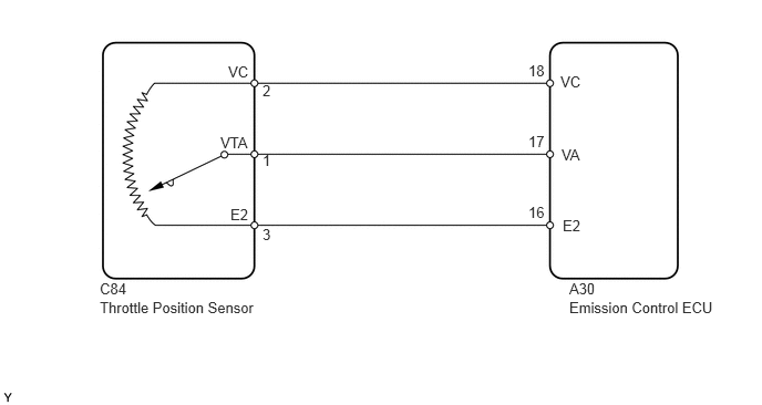
CAUTION / NOTICE / HINT
- HINT:
-
If DTC "22" (engine coolant temperature sensor circuit), "31" (vacuum sensor circuit) and "41" (throttle position sensor circuit) are output simultaneously, the E2 circuit (sensor ground) in the emission control ECU may be open.
PROCEDURE
Turn the ignition switch to ON.
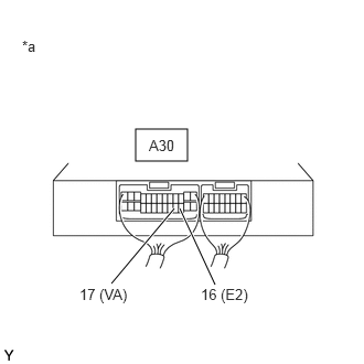
| *a | Component with harness connected (to Emission Control ECU) |
Measure the voltage according to the value(s) in thetable below.
- Standard Voltage:
-
Tester Connection Condition Specified Condition A30-17 (VA) - A30-16 (E2) Accelerator pedal fully released 2.6 to 3.8 V Accelerator pedal fully depressed 0.1 to 1.3 V
- Result:
-
Proceed to OK NG
OK
NG
Disconnect the throttle position sensor connector.
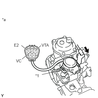
| *1 | Throttle Position Sensor |
| *a | Component without harness connected (Throttle Position Sensor) |
Measure the resistance according to the value(s) in the table below.
- Standard Resistance:
-
Tester Connection Condition Specified Condition 2 (VC) - 3 (E2) - 1.84 to 3.42 kΩ 1 (VTA) - 3 (E2) Accelerator pedal fully released 1.0 to 2.6 kΩ Accelerator pedal fully depressed 0.07 to 0.8 kΩ
- HINT:
-
The resistance between terminals 1 and 3 should change gradually in accordance with the accelerator pedal position.
- Result:
-
Proceed to OK NG
OK
NG
Disconnect the throttle position sensor connector.
Disconnect the emission control ECU connector.
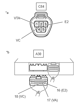
| *a | Front view of wire harness connector (to Throttle Position Sensor) |
| *b | Rear view of wire harness connector (to Emission Control ECU) |
Measure the resistance according to the value(s) in the table below.
- Standard Resistance:
-
Tester Connection Condition Specified Condition C84-1 (VTA) - A30-17 (VA) Always Below 1 Ω C84-2 (VC) - A30-18 (VC) Always Below 1 Ω C84-3 (E2) - A30-16 (E2) Always Below 1 Ω C84-1 (VTA) or A30-17 (VA) - Body ground Always 10 kΩ or higher C84-2 (VC) or A30-18 (VC) - Body ground Always 10 kΩ or higher C84-3 (E2) or A30-16 (E2) - Body ground Always 10 kΩ or higher
- Result:
-
Proceed to OK NG
OK
NG