1HZ ENGINE CONTROL ECD SYSTEM 31 Vacuum Sensor Circuit
DESCRIPTION
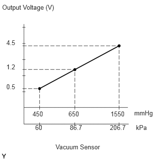
The diesel turbo pressure sensor detects the intake manifold pressure as a voltage by using a built-in sensor unit. The emission control ECU then determines the basic injection duration and basic ignition advance angle based on this voltage.
Since the diesel turbo pressure sensor does not use the atmospheric pressure as a criterion, but detects the absolute pressure inside the intake manifold (the pressure in proportion to the preset absolute vacuum 0), it is not influenced by fluctuations in the atmospheric pressure due to high altitude and other factors. This permits it to adjust the air fuel ratio to the proper level under all conditions.
| DTC No. | Detection Item | DTC Detection Condition | Trouble Area | Warning Indicate | Memory |
|---|---|---|---|---|---|
| 31 | Vacuum Sensor Circuit | Open or short in vacuum sensor circuit for 2 seconds or more |
·
Open or short in vacuum sensor circuit
·
Diesel turbo pressure sensor
·
emission control ECU |
Glow Indicator Light Comes on | DTC stored |
If the ECU detects diagnostic trouble code "31", it operates the fail-safe function, keeping the ignition timing and fuel injection volume constant and making it possible to drive the vehicle.
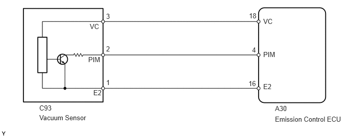
WIRING DIAGRAM
CAUTION / NOTICE / HINT
- HINT:
-
If DTC "22" (engine coolant temperature sensor circuit), "31" (vacuum sensor circuit) and "41" (throttle position sensor circuit) are output simultaneously, the E2 circuit (sensor ground) in the emission control ECU may be open.
PROCEDURE
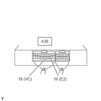
| *a | Component with harness connected (to Emission Control ECU) |
Measure the voltage according to the value(s) in thetable below.
- Standard Voltage:
-
Tester Connection Condition Specified Condition A30-18 (VC) - A30-16 (E2) Ignition switch ON 4.5 to 5.5 V
- Result:
-
Proceed to OK NG
OK
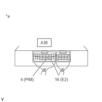
| *a | Component with harness connected (to Emission Control ECU) |
Measure the voltage according to the value(s) in thetable below.
- Standard Voltage:
-
Tester Connection Condition Specified Condition A30-4 (PIM) - A30-16 (E2) Negative pressure of 40 kPa (300 mmHg, 11.8 in.Hg) applied 1.0 to 1.2 V Same as atmospheric pressure 0.8 to 1.4 V Positive pressure of 78.5 kPa (0.8 kgf/cm2, 11.38 psi) applied 2.0 to 2.3 V
- Result:
-
Proceed to OK NG
OK
NG
Disconnect the diesel turbo pressure sensor connector.
Disconnect the emission control ECU connector.
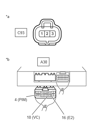
| *a | Front view of wire harness connector (to Diesel Turbo Pressure Sensor) |
| *b | Rear view of wire harness connector (to Emission Control ECU) |
Measure the resistance according to the value(s) in the table below.
- Standard Resistance:
-
Tester Connection Condition Specified Condition C93-2 (PIM) - A30-4 (PIM) Always Below 1 Ω C93-3 (VC) - A30-18 (VC) Always Below 1 Ω C93-1 (E2) - A30-16 (E2) Always Below 1 Ω C93-2 (PIM) or A30-4(PIM) - Body ground Always 10 kΩ or higher C93-3 (VC) or A30-18(VC) - Body ground Always 10 kΩ or higher C93-1 (E2) or A30-16 (E2) - Body ground Always 10 kΩ or higher
- Result:
-
Proceed to OK NG
OK
Click hereEngine / Hybrid System>1HZ (ENGINE CONTROL)>MANIFOLD ABSOLUTE PRESSURE SENSOR(w/ EGR System)>REMOVAL
NG