RM25T0E _51 Engine / Hybrid System _029759 1HZ ENGINE CONTROL _0135351 ECD SYSTEM J
1HZ ENGINE CONTROL ECD SYSTEM TC and CG Terminal Circuit
DESCRIPTION
Terminal TC is located in the DLC3.
The DLC3 is located in the vehicle interior. When terminal TC is connected with terminal CG, DTCs can be read from the glow indicator light in the combination meter assembly.
WIRING DIAGRAM
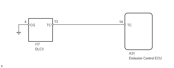
1.01,0.813 1.167,1 0.156,0.188 10 false 4 1.24,0.948 1.5,1.125 0.26,0.177 10 false CG 1.917,0.948 2.146,1.125 0.229,0.177 10 false TC 5.24,0.948 5.469,1.125 0.229,0.177 10 false TC 1.448,1.74 1.833,1.938 0.385,0.198 10 false I17 5.313,2.115 5.656,2.271 0.344,0.156 10 false A31 5.313,2.313 7.094,2.542 1.781,0.229 10 false Emission Control ECU 1.448,1.938 1.844,2.104 0.396,0.167 10 false DLC3 2.229,0.802 2.542,1 0.313,0.198 10 false 13 4.906,0.813 5.219,1.01 0.313,0.198 10 false 14
CAUTION / NOTICE / HINT
- HINT:
-
·
Even though terminal TC is not connected with terminal CG, the glow indicator light may blink.
·For the above phenomenon, the likely cause is an open or short in the wire harness, or malfunction inside the emission control ECU.
PROCEDURE
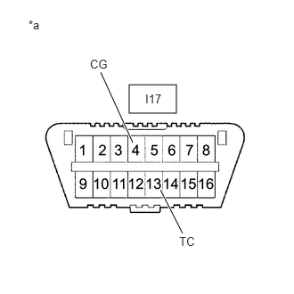
1.INSPECT DLC3
a.
1.51,0.99 2.063,1.323 0.552,0.333 1.875,2.219 2.135,2.729 true 1.552,1.667 1.177,0.844 true 0.333,0.208 1.115,0.677 0.781,0.469 10 false *a 2.094,2.74 2.354,2.917 0.26,0.177 10 false TC 1.052,0.667 1.313,0.844 0.26,0.177 10 false CG 1.698,1.073 2.021,1.24 0.323,0.167 10 false I17
| *a | Front view of wire harness connector (DLC3) |
Measure the voltage according to the value(s) in the table below.
- Standard Voltage:
-
Tester Connection Switch Condition Specified Condition I17-13 (TC) - I17-4 (CG) Ignition switch ON 11 to 14 V
- Result:
-
Proceed to OK NG
OK
REPLACE EMISSION CONTROL ECU
NG
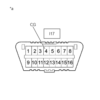
2.CHECK HARNESS AND CONNECTOR (DLC3 - BODY GROUND)
2.CHECK HARNESS AND CONNECTOR (DLC3 - BODY GROUND)
a.
1.51,0.99 2.063,1.323 0.552,0.333 1.542,1.677 1.125,0.906 true 0.333,0.208 1.115,0.677 0.781,0.469 10 false *a 1.031,0.76 1.292,0.938 0.26,0.177 10 false CG 1.688,1.073 2.01,1.24 0.323,0.167 10 false I17
| *a | Front view of wire harness connector (DLC3) |
Measure the resistance according to the value(s) in the table below.
- Standard Resistance:
-
Tester Connection Condition Specified Condition I17-4 (CG) - Body ground Always Below 1 Ω
- Result:
-
Proceed to OK NG
OK
3.CHECK HARNESS AND CONNECTOR (DLC3 - EMISSION CONTROL ECU)
NG
REPAIR OR REPLACE HARNESS OR CONNECTOR
3.CHECK HARNESS AND CONNECTOR (DLC3 - EMISSION CONTROL ECU)
a.
Disconnect the emission control ECU connector.
b.
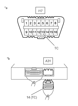
1.573,0.313 1.979,0.604 0.406,0.292 1.917,2.542 2.323,2.833 0.406,0.292 2.396,2.01 1.896,1.5 true 2.042,3.833 1.375,4.188 true 0.198,0.26 0.51,0.458 0.313,0.198 10 false *a 0.302,2.5 0.615,2.698 0.313,0.198 10 false *b 1.688,0.396 2.021,0.677 0.333,0.281 10 false I17 2,2.604 2.333,2.885 0.333,0.281 10 false A31 2.396,2.042 2.906,2.385 0.51,0.344 10 false TC 1.167,4.208 1.677,4.552 0.51,0.344 10 false 14 (TC)
| *a | Front view of wire harness connector (DLC3) |
| *b | Rear view of wire harness connector (to Emission Control ECU) |
Measure the resistance according to the value(s) in the table below.
- Standard Resistance:
-
Tester Connection Condition Specified Condition I17-13 (TC) - A31-14 (TC) Always Below 1 Ω I17-13 (TC) or A31-14 (TC) - Body ground Always 10 kΩ or higher
- Result:
-
Proceed to OK NG
OK
REPLACE EMISSION CONTROL ECU
NG
REPAIR OR REPLACE HARNESS OR CONNECTOR