1HZ ENGINE CONTROL ECD SYSTEM TERMINALS OF ECU
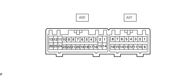
Measure the voltage according to the value(s) in the table below.
- HINT:
-
The standard voltage between each pair of emission control ECU terminals is shown in the table below. The appropriate conditions for checking each pair of terminals are also indicated.
-
The result of checks should be compared with the standard voltage for that pair of terminals, displayed in the Specified Condition column.
-
The illustration above can be used as a reference to identify the emission control ECU terminal locations.
| Terminal No. (Symbols) | Wiring Color | Terminal Description | Condition | Specified Condition |
|---|---|---|---|---|
| A31-1 (BATT) - A30-14 (E1) | P - BR | Battery (for measuring the battery voltage and for the emission control ECU memory) | Always | 11 to 14 V*1 22 to 28 V*2 |
| A30-25 (+B) - A30-14 (E1) | B-Y - BR | Ignition switch | Ignition switch ON | 11 to 14 V*1 22 to 28 V*2 |
| A30-18 (VC) - A30-16 (E2) | GR-R - BR-W | Power source of sensor (a specific voltage) | Ignition switch ON | 4.75 to 5.25 V |
| A30-17 (VA) - A30-16 (E2) | R-L - BR-W | Throttle position sensor | Throttle valve fully closed | 2.6 to 3.8 V |
| Throttle valve fully open | 0.1 to 1.3 V | |||
| A30-4 (PIM) - A30-16 (E2) | P-L - BR-W | Diesel turbo pressure sensor | Negative pressure of 40 kPa (300 mmHg, 11.8 in.Hg) applied | 1.0 to 1.2 V |
| Same as atmospheric pressure | 0.8 to 1.4 V | |||
| Positive pressure of 78.5 kPa (0.8 kgf/cm2, 11.38 psi) applied | 2.0 to 2.3 V | |||
| A30-3 (THW) - A30-16 (E2) | Y - BR-W | Engine coolant temperature sensor | Idling, engine coolant temperature 80°C (176°F) | 0.2 to 1.0 V |
| A30-2 (STA) - A30-14 (E1) | B-W - BR | Starter signal | Cranking | 6.0 V or more |
| A30-6 (NE+) - A30-19 (NE-) | R - G | Pickup sensor | Idling | Pulse generation (see waveform 1) |
| A31-5 (SP1) - A30-14 (E1) | G - BR | Speed signal from combination meter | Ignition switch ON, driving wheel rotated slowly | Pulse generation (see waveform 2) |
| A30-15 (EGR) - A30-14 (E1) | Y-R - BR | E-VRV for EGR | Ignition switch ON | 11 to 14 V*1 22 to 28 V*2 |
| Idling | Pulse generation (see waveform 3) |
|||
| A30-9 (VBAC) - A30-14 (E1) | R-B - BR | VSV for BACS | VSV OFF (idling) | 11 to 14 V*1 22 to 28 V*2 |
| VSV ON (engine warmed up and engine speed 3400 rpm or more) | 0 to 6 V | |||
| A30-13 (SREL) - A30-14 (E1) | R-B - BR | GLOW relay | Cranking | 11 to 14 V*1 22 to 28 V*2 |
| Idling (engine start after 600 sec.) | 0 to 3 V | |||
| A31-8 (GIND) - A30-14 (E1) | R-W - BR | Glow indicator light | Glow indicator light turns on | 0 to 6 V |
| Except when glow indicator light turns on | 11 to 14 V*1 22 to 28 V*2 |
|||
| A30-22 (VEGR) - A30-14 (E1) | Y-B - BR | VSV for EGR cut | VSV OFF (idling) | 11 to 14 V*1 22 to 28 V*2 |
| VSV ON | 0 to 3 V | |||
| A30-12 (TCV2) - A30-14 (E1) | B - BR | Timing control valve | Ignition switch ON | 11 to 14 V*1 22 to 28 V*2 |
| Idling with warm engine | Pulse generation (see waveform 4) |
|||
| A31-14 (TC) - A30-14 (E1) | G - BR | Terminal TC of DLC3 | Ignition switch ON | 11 to 14 V*1 22 to 28 V*2 |
*1: for 12 V battery
*2: for 24 V battery
WAVEFORM 1
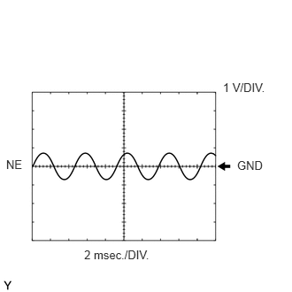
| ECU Terminal Name | Between NE+ and NE- |
| Tester Range | 1 V/DIV., 2 msec./DIV. |
| Condition | Idling with warm engine |
- HINT:
-
The waveform varies depending on the engine speed.
WAVEFORM 2
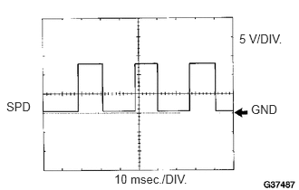
| ECU Terminal Name | Between SPD and E1 |
| Tester Range | 5 V/DIV., 10 msec./DIV. |
| Condition | Ignition switch ON, driving wheel rotated slowly |
- HINT:
-
The wavelength becomes shorter as the vehicle speed increases.
WAVEFORM 3
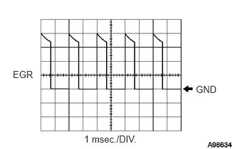
| ECU Terminal Name | Between EGR and E1 |
| Tester Range | 5 V/DIV., 1 msec./DIV.*1 10 V/DIV., 1 msec./DIV.*2 |
| Condition | Idling with warm engine |
*1: for 12 V battery
*2: for 24 V battery
WAVEFORM 4
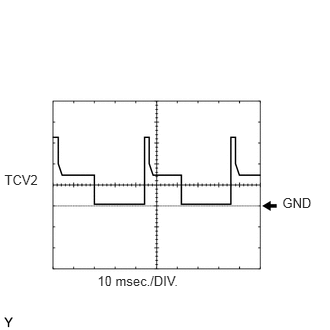
| ECU Terminal Name | Between TCV2 and E1 |
| Tester Range | 10 V/DIV., 10 msec./DIV.*1 20 V/DIV., 10 msec./DIV.*2 |
| Condition | Idling with warm engine |
*1: for 12 V battery
*2: for 24 V battery
- HINT:
-
The waveform varies depending on the engine speed.