Home › Engine / Hybrid System › 1HZ (ENGINE CONTROL) › ECD SYSTEM
RM25T0E _51 Engine / Hybrid System _029759 1HZ ENGINE CONTROL _0135351 ECD SYSTEM C

1HZ ENGINE CONTROL  ECD SYSTEM  43  Starter Signal Circuit Malfunction  


DESCRIPTION

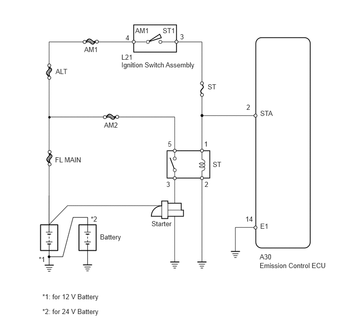
When the engine is being cranked, the intake airflow is slow, so fuel vaporization is poor. A rich mixture is therefore necessary in order to achieve good startability. While the engine is being cranked, positive battery voltage is applied to terminal STA of the emission control ECU. The starter signal is mainly used to increase the fuel injection volume for the starting injection control and after-start injection control.

DTC No. Detection Item DTC Detection Condition Trouble Area Warning Indicate Memory
43 Starter Signal Circuit Malfunction No starter signal to emission control ECU
·

Open or short in starter signal circuit

·

ST fuse

·

Emission control ECU


- DTC stored

WIRING DIAGRAM

A225221E02
5.302,5.333 6.792,5.542 1.49,0.208 10 false Emission Control ECU 5.302,5.156 5.677,5.323 0.375,0.167 10 false A30 5.313,4.531 5.542,4.688 0.229,0.156 10 false E1 5.313,2.229 5.635,2.375 0.323,0.146 10 false STA 4.24,1.688 4.448,1.844 0.208,0.156 10 false ST 2.479,1.24 4.24,1.49 1.76,0.25 10 false Ignition Switch Assembly 2.479,1.083 2.813,1.281 0.333,0.198 10 false L21 1.719,0.927 2.031,1.073 0.313,0.146 10 false AM1 1.135,1.375 1.427,1.531 0.292,0.156 10 false ALT 2.125,2.469 2.438,2.625 0.313,0.156 10 false AM2 1.125,3.177 1.729,3.344 0.604,0.167 10 false FL MAIN 2.042,4.75 2.521,4.917 0.479,0.167 10 false Battery 0.792,5.208 0.958,5.354 0.167,0.146 10 false *1 1.854,4.385 2.031,4.531 0.177,0.146 10 false *2 3.094,4.479 3.542,4.646 0.448,0.167 10 false Starter 4.344,3.271 4.552,3.427 0.208,0.156 10 false ST 0.865,5.969 2.146,6.167 1.281,0.198 10 false *1: for 12 V Battery 0.865,6.271 2.146,6.469 1.281,0.198 10 false *2: for 24 V Battery 3.677,0.667 3.781,0.833 0.104,0.167 10 false 3 2.563,0.688 2.688,0.865 0.125,0.177 10 false 4 3.323,0.542 3.594,0.708 0.271,0.167 10 false ST1 2.76,0.542 3.073,0.688 0.313,0.146 10 false AM1 5.031,2.104 5.167,2.281 0.135,0.177 10 false 2 5.01,4.385 5.198,4.552 0.188,0.167 10 false 14 3.427,2.854 3.563,3.031 0.135,0.177 10 false 5 4.167,2.854 4.302,3.031 0.135,0.177 10 false 1 3.396,3.677 3.531,3.854 0.135,0.177 10 false 3 4.177,3.677 4.313,3.854 0.135,0.177 10 false 2

CAUTION / NOTICE / HINT

NOTICE:

Inspect the fuses of circuits related to this system before performing the following inspection procedure.


PROCEDURE
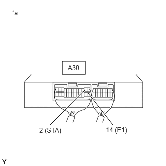
1.CHECK EMISSION CONTROL ECU (STA VOLTAGE)
a.
A190329C21
1.292,1.271 1.76,1.542 0.469,0.271 1.75,1.865 1.042,2.583 true 1.823,1.927 2.333,2.583 true 0.24,0.177 1.417,0.677 1.177,0.5 10 false *a 1.406,1.323 1.74,1.49 0.333,0.167 10 false A30 0.813,2.615 1.354,2.813 0.542,0.198 10 false 2 (STA) 2.188,2.604 2.677,2.802 0.49,0.198 10 false 14 (E1)
*a Component with harness connected
(to Emission Control ECU)


Measure the voltage according to the value(s) in thetable below.

Standard Voltage:
Tester Connection Condition Specified Condition
A30-2 (STA) - A30-14 (E1) Ignition switch ON 0 V
Cranking 6 V or more


Result:
Proceed to
OK
NG


OK

NG

2.CHECK HARNESS AND CONNECTOR (IGNITION SWITCH ASSEMBLY - EMISSION CONTROL ECU)
a.

Disconnect the ignition switch assembly connector.


b.

Disconnect the emission control ECU connector.


c.

Measure the resistance according to the value(s) in the table below.

Standard Resistance:
Tester Connection Condition Specified Condition
L21-3 (ST1) - A30-2 (STA) Always Below 1 Ω
L21-3 (ST1) or A30-2 (STA) - Body ground Always 10 kΩ or higher


Result:
Proceed to
OK
NG


OK

NG

REPAIR OR REPLACE HARNESS OR CONNECTOR