Home › Engine / Hybrid System › 1HZ (ENGINE CONTROL) › ECD SYSTEM
RM25T0E _51 Engine / Hybrid System _029759 1HZ ENGINE CONTROL _0135351 ECD SYSTEM C

1HZ ENGINE CONTROL  ECD SYSTEM  51  Switch Condition Signal Circuit  


DESCRIPTION

The emission control ECU uses the output from the air conditioning switch to determine whether or not the air conditioning is operating so that it can increase the idling speed of the engine if necessary.

DTC No. Detection Item DTC Detection Condition Trouble Area Warning Indicate Memory
51 Switch Condition Signal Circuit A/C switch ON, engine started, idle switch OFF
·

A/C amplifier circuit

·

A/C COMP relay

·

A/C amplifier

·

Emission control ECU


- -

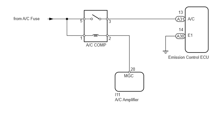
WIRING DIAGRAM

A190480E04
4.333,2.208 4.563,2.365 0.229,0.156 10 false 20 3.813,3.219 4.74,3.385 0.927,0.167 10 false A/C Amplifier 2.656,0.604 2.771,0.76 0.115,0.156 10 false 5 5.917,0.323 6.135,0.5 0.219,0.177 10 false 13 5.865,1.115 6.167,1.313 0.302,0.198 10 false A30 5.927,0.896 6.146,1.073 0.219,0.177 10 false 14 5.875,0.552 6.208,0.729 0.333,0.177 10 false A31 5.583,1.813 7.052,1.99 1.469,0.177 10 false Emission Control ECU 6.229,0.542 6.531,0.698 0.302,0.156 10 false A/C 6.229,1.083 6.469,1.25 0.24,0.167 10 false E1 3.813,3.052 4.094,3.229 0.281,0.177 10 false I11 4.115,2.427 4.5,2.594 0.385,0.167 10 false MGC 3.604,1.188 3.719,1.344 0.115,0.156 10 false 2 2.656,1.177 2.771,1.333 0.115,0.156 10 false 1 3.604,0.625 3.719,0.771 0.115,0.146 10 false 3 2.854,1.406 3.583,1.573 0.729,0.167 10 false A/C COMP 0.448,0.531 1.458,0.698 1.01,0.167 10 false from A/C Fuse

PROCEDURE

1.CHECK DTC OUTPUT
a.

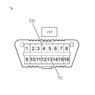
Connect terminals TC and CG of the DLC3.


b.

Turn the ignition switch to ON.


c.
A191618C03
1.51,0.99 2.063,1.323 0.552,0.333 1.875,2.219 2.135,2.729 true 1.552,1.667 1.177,0.844 true 0.333,0.208 1.115,0.677 0.781,0.469 10 false *a 2.094,2.74 2.354,2.917 0.26,0.177 10 false TC 1.052,0.667 1.313,0.844 0.26,0.177 10 false CG 1.708,1.083 2.031,1.25 0.323,0.167 10 false I17
*a Front view of wire harness connector
(DLC3)


Turn the A/C switch ON and OFF and check if DTC 51 isoutput by the glow indicator light.

OK:
Tester Connection Condition Specified Condition
I17-13 (TC) - I17-4 (CG) A/C switch ON DTC 51 output
A/C switch OFF No DTC output


Result:
Proceed to
OK
NG


OK

NG

2.INSPECT EMISSION CONTROL ECU
a.
A191618C04
1.51,0.99 2.063,1.323 0.552,0.333 1.875,2.219 2.135,2.729 true 1.552,1.667 1.177,0.844 true 0.333,0.208 1.115,0.677 0.781,0.469 10 false *a 2.094,2.74 2.354,2.917 0.26,0.177 10 false TC 1.052,0.667 1.313,0.844 0.26,0.177 10 false CG 1.688,1.083 2.01,1.25 0.323,0.167 10 false I17
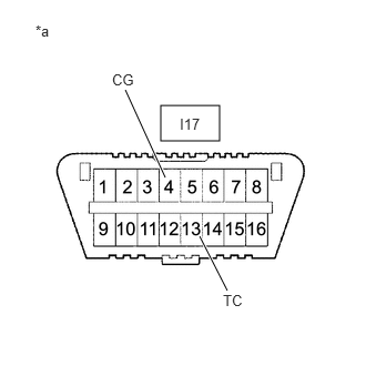
*a Front view of wire harness connector
(DLC3)


Connect terminals TC and CG of the DLC3.


b.

Turn the ignition switch to ON.


c.
A190329C16
1.292,1.302 1.76,1.573 0.469,0.271 1.906,1.302 2.365,1.573 0.458,0.271 1.823,1.948 1.729,2.771 true 2.083,1.958 2.396,2.604 true 0.313,0.115 1.458,0.594 1.146,0.479 10 false *a 1.406,1.354 1.74,1.521 0.333,0.167 10 false A30 1.563,2.865 2.219,3.063 0.656,0.198 10 false 14 (E1) 2.24,2.635 2.813,2.833 0.573,0.198 10 false 13 (A/C) 2.01,1.354 2.302,1.521 0.292,0.167 10 false A31
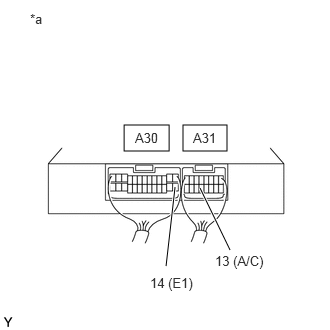
*a Rear view of wire harness connector
(to Emission Control ECU)


When the A/C switch is OFF, check the emission control ECU voltage and check if DTC 51 is output by the glow indicator light.

Result:
Tester Connection Condition Proceed to
A31-13 (A/C) is 0 V and DTC 51 is output A/C switch OFF A
A31-13 (A/C) is 12 V and DTC 51 is output A/C switch OFF B


B

3.INSPECT A/C COMP RELAY

A

3.INSPECT A/C COMP RELAY

Result:
Proceed to
OK
NG


OK

4.CHECK HARNESS AND CONNECTOR (ENGINE ROOM RELAY BLOCK ASSEMBLY - A/C AMPLIFIER)

NG

REPLACE A/C COMP RELAY

4.CHECK HARNESS AND CONNECTOR (ENGINE ROOM RELAY BLOCK ASSEMBLY - A/C AMPLIFIER)
a.

Remove the A/C COMP relay from the engine room relay block assembly.


b.

Disconnect the A/C amplifier connector.


c.

Measure the resistance according to the value(s) in the table below.

Standard Resistance:
Tester Connection Condition Specified Condition
A/C COMP relay terminal (2) - I11-20 (MGC) Always Below 1 Ω
A/C COMP relay terminal (2) or I11-20 (MGC) - Body ground Always 10 kΩ or higher


Result:
Proceed to
OK
NG


OK

REPLACE A/C AMPLIFIER

NG

REPAIR OR REPLACE HARNESS OR CONNECTOR