1HZ ENGINE CONTROL ECD SYSTEM Timing Control Valve Circuit
DESCRIPTION
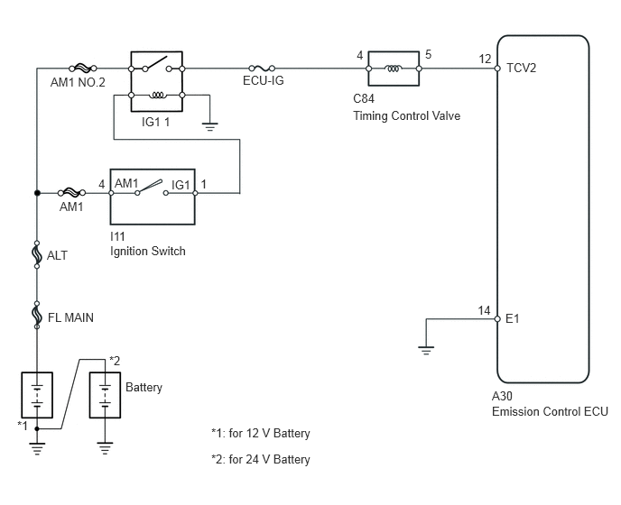
The Timing Control Valve (TCV) inside the injection pump is turned ON/OFF by the emission control ECU.
When the ignition switch is ON, battery voltage is continuously applied to the +B terminal of the TCV. The circuit of the TCV2 terminal is open or closed on the emission control ECU side. The TCV will switch the fuel injection timing to the advance or retarded side. (When the TCV is connected, it is on the advance side.)
- HINT:
-
If the TCV has a failure and is stuck either on the advance side or the retarded side, the following conditions will occur.
-
·
Retarded side: Black smoke occurs. When starting, misfiring occurs.
·Advance side: Noise (diesel knock) will become greater.
WIRING DIAGRAM
- HINT:
-
2 connector pins of the Timing Control Valve (TCV) are branched from the 5 connector pins of the throttle sensor in the injection pump.
CAUTION / NOTICE / HINT
- NOTICE:
-
Inspect the fuses of circuits related to this system before performing the following inspection procedure.
PROCEDURE
Disconnect the timing control valve connector.
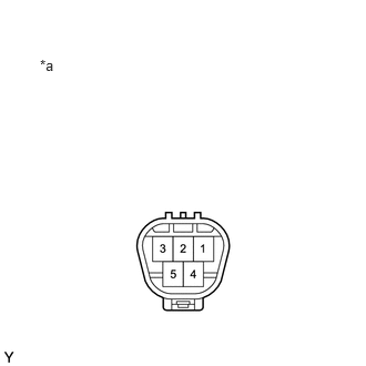
| *a | Component without harness connected (Timing Control Valve) |
Measure the resistance according to the value(s) in thetable below.
- Standard Resistance:
-
Tester Connection Condition Specified Condition 4 - 5 20°C (68°F) 11.3 Ω
Apply battery voltage across terminals 4 and 5 of the timing control valve.
- NOTICE:
-
Do not start the engine.
Check whether there is any operation noise from the injection pump when switching the voltage ON/OFF.
- OK:
-
Operation noise can be heard.
- Result:
-
Proceed to OK NG
OK
NG
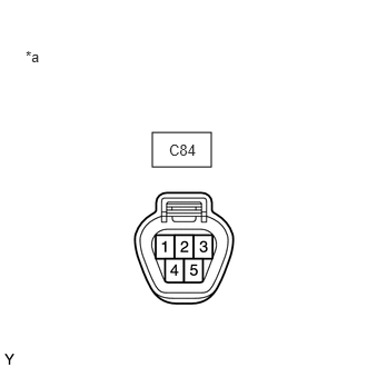
| *a | Front view of wire harness connector (to Timing Control Valve) |
Measure the voltage according to the value(s) in the table below.
- Standard Voltage:
-
Tester Connection Switch Condition Specified Condition C84-4 - Body ground Ignition switch ON 11 to 14 V*1
22 to 28 V*2
*1: for 12 V battery
*2: for 24 V battery
- Result:
-
Proceed to OK NG
OK
NG
Disconnect the emission control ECU connector.
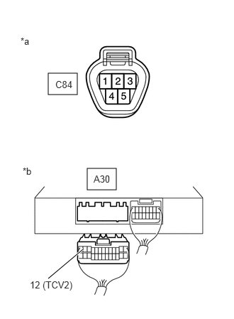
| *a | Front view of wire harness connector (to Timing Control Valve) |
| *b | Rear view of wire harness connector (to Emission Control ECU) |
Measure the resistance according to the value(s) in the table below.
- Standard Resistance:
-
Tester Connection Condition Specified Condition C84-5 - A30-12 (TCV2) Always Below 1 Ω C84-5 or A30-12 (TCV2) - Body ground Always 10 kΩ or higher
- Result:
-
Proceed to OK NG
OK
NG
Disconnect the timing control valve connector.
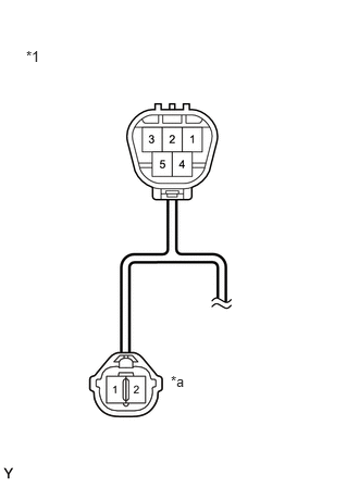
| *1 | Timing control valve wire (Injection Pump) |
| *a | Timing control valve connector |
Measure the resistance according to the value(s) in the table below.
- Standard Resistance:
-
Tester Connection Condition Specified Condition 4 - Timing control valve connector 1 Always Below 1 Ω 5 - Timing control valve connector 2 Always Below 1 Ω
- Result:
-
Proceed to OK NG
OK
NG
Detach the clamp and remove the bolt.
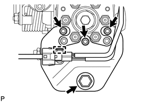
Remove the 3 hexagon bolts and injection pump stay.
Disconnect the timing control valve connector.
Remove the 2 hexagon bolts and timing control valve.
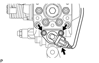
Install a new timing control valve with the 2 hexagon bolts.
- Torque:
- 8.4 N*m (86 kgf*cm, 74 in.*lbf)
Connect the timing control valve connector.
Install the injection pump stay with the 3 hexagon bolts.
- Torque:
- 8.4 N*m (86 kgf*cm, 74 in.*lbf)
Install the bolt and attach the clamp.
Bleed air from the fuel system.
- Result:
-
Proceed to NEXT
NEXT