RM25T0E _51 Engine / Hybrid System _029759 1HZ ENGINE CONTROL _0135351 ECD SYSTEM J
1HZ ENGINE CONTROL ECD SYSTEM BACS Control Circuit
DESCRIPTION
The VSV for BACS reduces the excessive smoke caused by rapid acceleration during EGR operation.
WIRING DIAGRAM
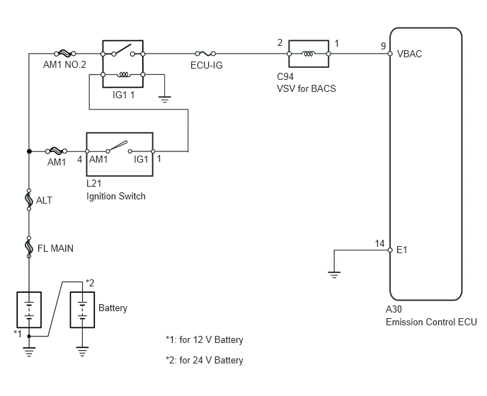
1.271,2.615 1.646,2.792 0.375,0.177 10 false L21 1.271,2.802 2.188,2.979 0.917,0.177 10 false Ignition Switch 5.51,3.5 5.688,3.677 0.177,0.177 10 false 14 5.833,3.594 6.021,3.771 0.188,0.177 10 false E1 5.677,4.469 6.042,4.646 0.365,0.177 10 false A30 5.677,4.656 7.146,4.865 1.469,0.208 10 false Emission Control ECU 0.698,2.302 1,2.479 0.302,0.177 10 false AM1 2.802,0.875 3.479,1.052 0.677,0.177 10 false ECU-IG 1.656,1.313 2.188,1.5 0.531,0.188 10 false IG1 1 0.635,0.865 1.49,1.031 0.854,0.167 10 false AM1 NO.2 0.531,2.865 0.813,3.052 0.281,0.188 10 false ALT 0.552,3.573 1.135,3.729 0.583,0.156 10 false FL MAIN 1.448,4.448 1.927,4.615 0.479,0.167 10 false Battery 0.198,4.833 0.365,4.979 0.167,0.146 10 false *1 1.26,4.083 1.438,4.229 0.177,0.146 10 false *2 2.438,4.917 3.875,5.115 1.438,0.198 10 false *1: for 12 V Battery 2.438,5.219 3.885,5.417 1.448,0.198 10 false *2: for 24 V Battery 5.844,0.708 6.26,0.865 0.417,0.156 10 false VBAC 4.073,1.042 4.604,1.198 0.531,0.156 10 false C94 4.073,1.219 5.01,1.365 0.938,0.146 10 false VSV for BACS 5.604,0.594 5.823,0.74 0.219,0.146 10 false 9 2.302,2.25 2.406,2.427 0.104,0.177 10 false 1 1.135,2.26 1.25,2.417 0.115,0.156 10 false 4 1.313,2.26 1.635,2.427 0.323,0.167 10 false AM1 1.969,2.26 2.25,2.417 0.281,0.156 10 false IG1 4.917,0.552 5.063,0.75 0.146,0.198 10 false 1 4.083,0.542 4.219,0.74 0.135,0.198 10 false 2
CAUTION / NOTICE / HINT
- NOTICE:
-
Inspect the fuses of circuits related to this system before performing the following inspection procedure.
PROCEDURE
1.INSPECT VACUUM SWITCHING VALVE (for BACS)
a.
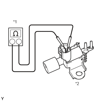
Disconnect the VSV for BACS connector.
b.
0.448,0.656 1.156,0.802 0.708,0.146 10 false *1 2.563,2.76 3,3.167 0.438,0.406 10 false *2
| *1 | Ohmmeter |
| *2 | VSV for BACS |
Measure the resistance according to the value(s) in the table below.
- Standard Resistance:
-
Tester Connection Condition Specified Condition 1 - 2 20°C (68°F) 33 to 39 Ω*1
135 to 155 Ω*2
*1: for 12 V battery
*2: for 24 V battery
c.
0.208,0.646 0.521,0.844 0.313,0.198 10 false *1 0.406,3.448 0.719,3.646 0.313,0.198 10 false *2 2.74,0.104 3.198,0.302 0.458,0.198 10 false Air 2.99,2.427 3.271,2.698 0.281,0.271 10 false Air 2.115,0.604 2.427,0.802 0.313,0.198 10 false E 2.646,3 2.958,3.198 0.313,0.198 10 false E 3.125,3.229 3.344,3.635 0.219,0.406 10 false F
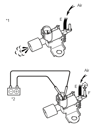
| *1 | VSV for BACS |
| *2 | Battery |
Inspect the VSV for BACS operation.
- OK:
-
Tester Connection Condition Specified Condition 1 - 2 No battery voltage applied Air flows from port E to filter Battery voltage applied across terminals Air flows from port E to F
- Result:
-
Proceed to OK NG
OK
2.INSPECT VACUUM SWITCHING VALVE (for BACS)
NG
REPLACE VSV FOR BACS
2.INSPECT VACUUM SWITCHING VALVE (for BACS)
a.
Disconnect the emission control ECU connector.
b.
Turn the ignition switch to ON.
c.
1.271,0.198 1.688,0.458 0.417,0.26 0.688,1.917 1.406,1.302 true 1.948,3.99 2.26,4.188 0.313,0.198 10 false *2 0.094,0.188 0.406,0.385 0.313,0.198 10 false *a 0.188,2.417 0.5,2.615 0.313,0.198 10 false *1 0.771,4.188 1.083,4.385 0.313,0.198 10 false *b 2.469,4.24 2.781,4.438 0.313,0.198 10 false *c 1.219,2.896 1.531,3.094 0.313,0.198 10 false E 2.823,2.938 3.135,3.135 0.313,0.198 10 false E 1.563,2.875 1.875,3.073 0.313,0.198 10 false F 0.458,1.938 1.688,2.135 1.229,0.198 10 false 9 (VBAC) 1.375,0.25 1.688,0.448 0.313,0.198 10 false A30
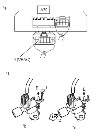
| *1 | VSV for BACS |
| *2 | Air Filter |
| *a | Rear view of wire harness connector (to Emission Control ECU) |
| *b | VSV: ON |
| *c | VSV: OFF |
Check the VSV for BACS operation.
- OK:
-
Condition Specified Condition A30-9 (VBAC) and body ground are connected, VSV is ON Air from pipe E flows out through pipe F A30-9 (VBAC) and body ground are not connected, VSV is OFF Air from pipe E flows out through air filter
- Result:
-
Proceed to OK NG
OK
REPLACE EMISSION CONTROL ECU
NG
3.CHECK HARNESS AND CONNECTOR (VACUUM SWITCHING VALVE FOR BACS - EMISSION ECU)
3.CHECK HARNESS AND CONNECTOR (VACUUM SWITCHING VALVE FOR BACS - EMISSION ECU)
a.
Disconnect the VSV for BACS connector.
b.
Disconnect the emission control ECU connector.
c.
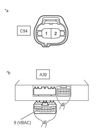
1.229,2.344 1.667,2.656 0.438,0.313 0.583,0.875 1.021,1.188 0.438,0.313 0.698,4.021 1.427,3.615 true 0.156,0.271 0.469,0.469 0.313,0.198 10 false *a 0.219,2.365 0.531,2.563 0.313,0.198 10 false *b 1.333,2.427 1.646,2.625 0.313,0.198 10 false A30 0.677,0.958 0.99,1.156 0.313,0.198 10 false C94 0.469,4.042 1.698,4.24 1.229,0.198 10 false 9 (VBAC)
| *a | Front view of wire harness connector (to VSV for BACS) |
| *b | Rear view of wire harness connector (to Emission Control ECU) |
Measure the resistance according to the value(s) in the table below.
- Standard Resistance:
-
Tester Connection Condition Specified Condition C94-1 - A30-9 (VBAC) Always Below 1 Ω C94-1 or A30-9 (VBAC) - Body ground Always 10 kΩ or higher
- Result:
-
Proceed to OK NG
OK
REPAIR OR REPLACE HARNESS OR CONNECTOR (ECU-IG FUSE - VSV FOR BACS)
NG
REPAIR OR REPLACE HARNESS OR CONNECTOR