RM25T0E _51 Engine / Hybrid System _029769 1HZ EMISSION CONTROL _0135390 VACUUM REGULATING VALVE G
1HZ EMISSION CONTROL VACUUM REGULATING VALVE INSPECTION
PROCEDURE

 25819 1.INSPECT VACUUM REGULATING VALVE ASSEMBLY
a.
Measure the resistance according to the value(s) in the table below.
- Standard Resistance:
-
Tester Connection Condition Specified Condition 1 - 2 20°C (68°F) 11 to 13 Ω 1 - Body ground
2 - Body ground20°C (68°F) 10 MΩ or higher
If the result is not as specified, replace the vacuum regulating valve assembly.
b.
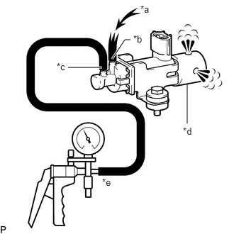
2.75,1.229 2.75,1.813 false 1.646,0.865 1.833,0.583 1.833,0.583 1.917,0.583 true 1.5,0.99 1,0.99 true 2.063,0.052 2.375,0.208 0.313,0.156 10 false *a 0.833,0.896 1.146,1.052 0.313,0.156 10 false *c 1.958,0.49 2.271,0.646 0.313,0.156 10 false *b 2.688,1.844 3,2 0.313,0.156 10 false *d 1.5,2.594 1.813,2.75 0.313,0.156 10 false *e
| *a | Air |
| *b | Port E |
| *c | Port F |
| *d | Filter |
| *e | Vacuum |
Check the operation of the vacuum regulating valve assembly.
i.
When a vacuum of 67 kPa (500 mmHg, 19.7 in.Hg) is applied to port F, check that air flows from port E to the filter.
ii.
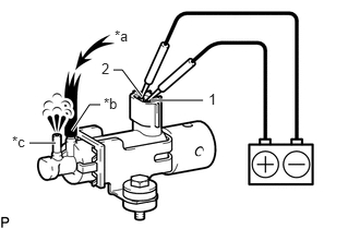
0.688,1.25 0.854,1 0.854,1 0.958,1 true 0.531,1.365 0.281,1.365 true 1.438,0.958 1.938,0.958 true 1.354,0.917 1.167,0.667 1.167,0.667 1.083,0.667 true 1.094,0.26 1.406,0.417 0.313,0.156 10 false *a 0.99,0.906 1.302,1.063 0.313,0.156 10 false *b 0.115,1.271 0.427,1.427 0.313,0.156 10 false *c 1.99,0.865 2.302,1.021 0.313,0.156 10 false 1 0.969,0.573 1.281,0.729 0.313,0.156 10 false 2
| *a | Air |
| *b | Port E |
| *c | Port F |
Apply battery voltage across terminals 1 and 2.
iii.
Check that air flows from port E to port F.
If the result is not as specified, replace the vacuum regulating valve assembly.