1HZ FUEL FUEL INJECTION PUMP REASSEMBLY
PROCEDURE

 1. MOUNT PUMP ASSEMBLY TO SST
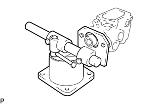
- SST
-
09241-76022
09245-54010
2.INSTALL OIL SEAL
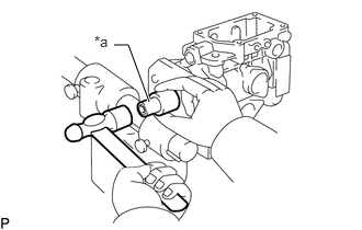
| *a | 22 mm Socket Wrench |
Apply MP grease to the lip of a new oil seal.
Using a 22 mm socket wrench, tap in the oil seal until its surface is flush with the pump housing.
3.INSTALL FUEL INLET HOLLOW SCREW
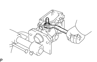
Install a new gasket and the hollow screw.
- Torque:
- 36.8 N*m (375 kgf*cm, 27 ft.*lbf)
22180 4.INSTALL REGULATOR VALVE
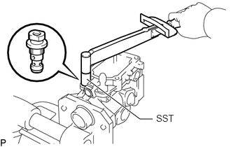
Install the 2 O-rings to the regulator valve.
Using SST, install the regulator valve.
- SST
-
09260-54012 (09262-54020)
- Torque:
- 8.8 N*m (90 kgf*cm, 78 in.*lbf)
5.INSTALL FUEL FEED PUMP
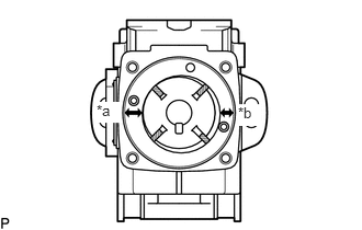
| *a | Wide |
| *b | Narrow |
Install the liner, rotor and 4 blades.
Check that the liner and blades are facing in the correct direction as shown in the illustration.
Check that the blades move smoothly.
Align the fuel outlet holes of the cover and liner.
Install the pump cover with the 2 screws.
- Torque:
- 2.95 N*m (30 kgf*cm, 26 in.*lbf)
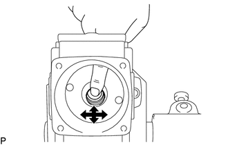
Check that the rotor moves smoothly.
6.INSTALL DRIVE SHAFT
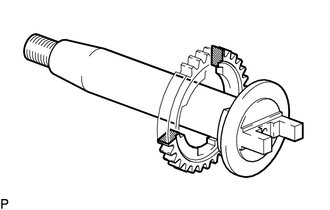
Install the drive gear on the drive shaft as shown in the illustration.
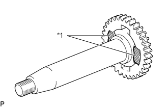
| *1 | Joint Rubber |
Install 2 new joint rubbers into the drive gear.
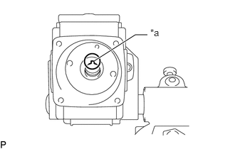
| *a | Key Groove |
Position the key groove of the feed pump rotor upward.
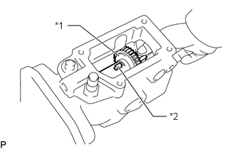
| *1 | Drive Shaft Washer |
| *2 | Set Key |
Install the set key and drive shaft washer on the drive shaft and insert the drive shaft assembly into the pump housing.
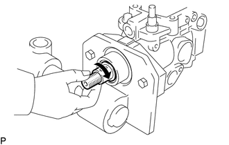
Check that the drive shaft turns without catching.
22582 7.INSTALL TIMER PISTON
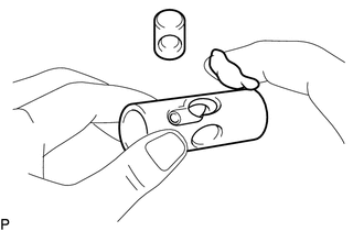

|
High-temperature grease |
Apply high-temperature grease to the timer piston and sub-piston.
Install the sub-piston into the timer piston.
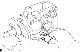
Insert the timer piston into the pump housing.
22108A 8.INSTALL ROLLER RING
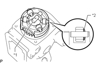
| *1 | Slide Pin |
| *2 | Washer |
Install the slide pin, 4 rollers and washers on the roller ring.
Check that the roller is facing the flat surface of the washer.
Install the roller ring into the pump housing.
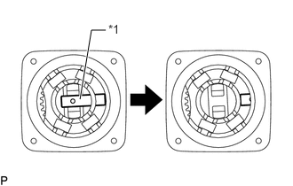
| *1 | Slide Pin |
Carefully install the slide pin into the sub-piston.
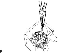
Install the stopper pin and clip.
9.INSTALL TIMER SPRING
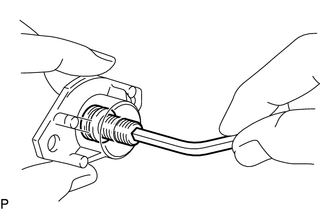
Install a new O-ring to the timer adjusting screw.
Using a 5 mm hexagon wrench, install the timer adjusting screw to the LH timer cover and temporarily install the nut.
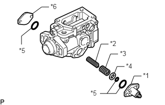
| *1 | LH Timer Cover |
| *2 | Timer Inner Spring |
| *3 | Timer Outer Spring |
| *4 | Timer Shim |
| *5 | O-ring |
| *6 | RH Timer Cover |
Install the following parts:
New O-ring
RH timer cover
Timer outer spring
Timer inner spring
Timer shim
New O-ring
LH timer cover, timer adjusting screw and nut assembly
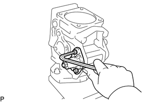
Using a 5 mm hexagon wrench, install the 4 bolts.
- Torque:
- 8.4 N*m (86 kgf*cm, 74 in.*lbf)
10.PRESET TIMER ADJUSTING SCREW
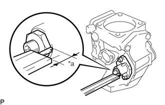
| *a | Protrusion |
Using a vernier caliper, measure the protrusion of the adjusting screw from the timer cover.
- Standard Protrusion:
-
7.5 to 8.0 mm (0.295 to 0.315 in.)
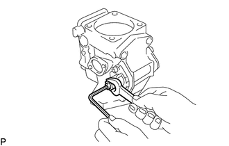
Using a 5 mm hexagon wrench, adjust the protrusion of the adjusting screw from the timer cover.
- Torque:
- 14.2 N*m (145 kgf*cm, 10 ft.*lbf)
11.ADJUST PLUNGER SPRING SHIM
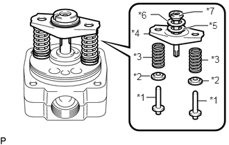
| *1 | Plunger Spring Guide |
| *2 | Upper Spring Seat |
| *3 | Plunger Spring |
| *4 | Lower Spring Seat |
| *5 | Upper Plunger Plate |
| *6 | Lower Plunger Plate |
| *7 | Pump Plunger |
Install the following parts to the distributive head:
2 plunger spring guides
2 upper spring seats
2 plunger springs
Lower spring seat
Upper plunger plate
Lower plunger plate
Pump plunger
- HINT:
-
Do not assemble the plunger spring shim at this time.
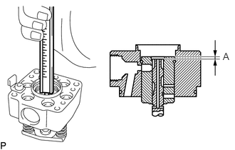
Using a vernier caliper, measure clearance A indicated in the illustration.
- Plunger Spring Shim Selection Chart:
-
Measured Clearance Shim Thickness More than 5.3 mm (0.209 in.) 0.5 mm (0.0197 in.) 5.0 to 5.2 mm (0.196 to 0.205 in.) 0.8 mm (0.0315 in.) 4.8 to 4.9 mm (0.189 to 0.193 in.) 1.0 mm (0.0394 in.) 4.6 to 4.7 mm (0.181 to 0.185 in.) 1.2 mm (0.0472 in.) 4.3 to 4.5 mm (0.169 to 0.177 in.) 1.5 mm (0.0591 in.) 4.0 to 4.2 mm (0.157 to 0.165 in.) 1.8 mm (0.0709 in.) Less than 3.9 mm (0.154 in.) 2.0 mm (0.0787 in.)
- HINT:
-
·
For a measurement between listed sizes, use the next largest size. Ex. If thickness is 1.1 mm (0.0433 in.) by calculation, use a 1.2 mm (0.0472 in.) shim.
·Select 2 shims which have the same thickness.
12.INSTALL COUPLING
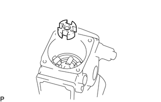
Install the coupling.
13.INSTALL FACE CAMPLATE
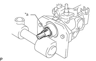
| *a | Key Groove |
Face the drive shaft with the key groove facing upward.
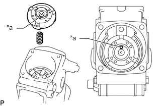
| *a | Pin |
Install the coupling spring and camplate with the camplate pin facing the governor cover side.
14.INSTALL GOVERNOR LINK
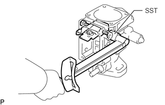
Using SST, install the governor link with 2 new gaskets and the 2 support bolts.
- SST
-
09260-54012 (09269-54040)
- Torque:
- 14 N*m (143 kgf*cm, 10 ft.*lbf)
Check that the governor link moves smoothly.
15.INSTALL PUMP PLUNGER
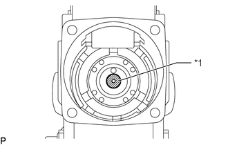
| *1 | Plunger Adjusting Shim |
Place the previously used plunger adjusting shim on the center of the camplate.
- NOTICE:
-
Do not apply grease to the shim.
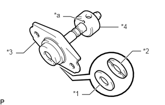
| *1 | Lower Plunger Plate |
| *2 | Upper Plunger Plate |
| *3 | Lower Spring Seat |
| *4 | Spill Ring |
| *a | Hole |
Install the following parts to the pump plunger:
Lower plunger plate
Upper plunger plate
Lower spring seat
Spill ring
- HINT:
-
Face the spill ring with the hole facing the lower spring seat.
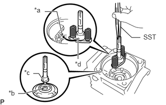
| *a | Ball Pin |
| *b | Pin |
| *c | Pin Groove |
| *d | Pin Hole |
Align the pin groove of the plunger with the pin of the face camplate.
Align the ball pin of the governor link with the pin hole of the spill ring.
Using SST, install the pump plunger and 2 plunger springs.
- SST
-
09260-54012 (09269-54030)
22140 16.INSTALL DISTRIBUTIVE HEAD
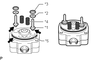
| *1 | Plunger Spring Guide |
| *2 | New Selected Plunger Spring Shim |
| *3 | Upper Spring Seat |
| *4 | Lever Support Spring |
| *5 | New O-ring |
|
|
High-temperature grease |
Apply high-temperature grease to the 2 plunger spring guides and O-ring.
Install the following parts to the distributive head:
2 plunger spring guides
2 new selected plunger spring shims
2 upper spring seats
2 lever support springs
New O-ring
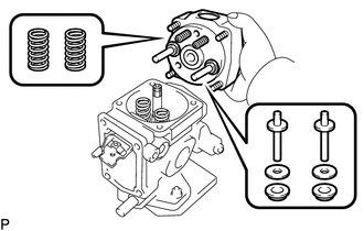
Install the distributive head.
- NOTICE:
-
Be careful not to damage the pump plunger.
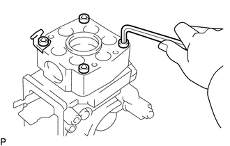
Using a 5 mm hexagon wrench, install the 4 bolts and wire clip.
- Torque:
- 12 N*m (122 kgf*cm, 9 ft.*lbf)
- HINT:
-
Use a bolt that is 45 mm (1.77 in.) in length.
17.INSTALL DELIVERY VALVE HOLDERS
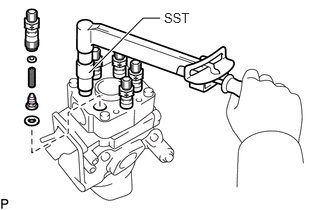
Install new gaskets and the valves into the distributive head.
Install the spring seats and springs into the delivery valve holders.
Using SST, install the delivery valve holders.
- SST
-
09260-54012 (09269-54020)
- Torque:
- 58.9 N*m (601 kgf*cm, 43 ft.*lbf)
18.INSTALL GOVERNOR SHAFT AND FLYWEIGHT HOLDER
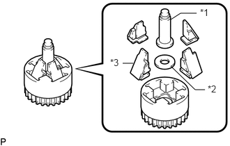
| *1 | Governor Sleeve |
| *2 | No. 2 Flyweight Washer |
| *3 | Flyweight |
Install the following parts to the flyweight holder:
4 flyweights
No. 2 flyweight washer
Governor sleeve
- HINT:
-
Replace the 4 flyweights as a set.
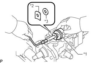
| *1 | Flyweight Holder Assembly |
| *2 | No. 1 Flyweight Washer |
| *3 | Governor Gear Adjusting Washer |
Install a new O-ring to the governor shaft.
Place the flyweight holder assembly (1) in position, and install the No. 1 flyweight washer (2) and governor gear adjusting washer (3) between the flyweight holder and pump housing.
Install the governor shaft through the governor gear adjusting washer, No. 1 flyweight washer and flyweight holder assembly.
Using a 5 mm hexagon wrench, turn the governor shaft counterclockwise.
19.CHECK FLYWEIGHT HOLDER THRUST CLEARANCE
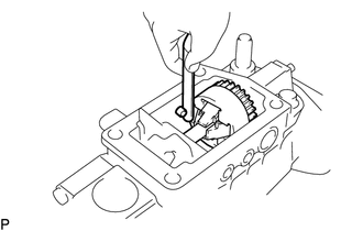
Using a thickness gauge, measure the thrust clearance between the housing pin and flyweight holder.
- Standard Thrust clearance:
-
0.15 to 0.35 mm (0.0591 to 0.0138 in.)
- HINT:
-
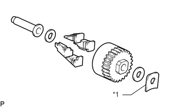 2.49,1.938 2.667,1.938 2.667,1.938 2.969,1.729 false 2.292,1.844 2.5,2.031 0.208,0.188 10 false *1
*1 Adjusting Washer
-
If the thrust clearance is not as specified, adjust with a governor gear adjusting washer.
- Governor gear adjusting washer thickness:
-
1.05 mm (0.0413 in.)
1.25 mm (0.0492 in.)
1.45 mm (0.0571 in.)
1.65 mm (0.0650 in.)
1.85 mm (0.0728 in.)
22740 20.ADJUST PROTRUSION OF GOVERNOR SHAFT
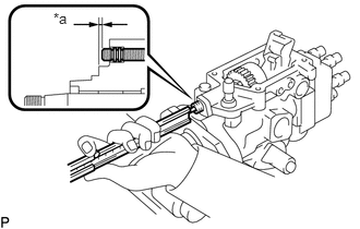
| *a | Protrusion |
Using a vernier caliper, measure the protrusion of the governor shaft.
- Standard Protrusion:
-
0.5 to 2.0 mm (0.0197 to 0.0787 in.)
If the protrusion is not as specified, adjust by turning the governor shaft.
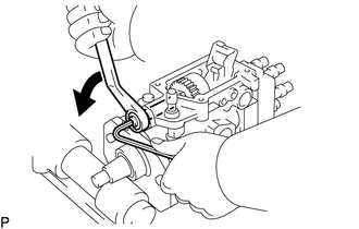
Install and tighten the nut while holding the governor shaft with a 5 mm hexagon wrench.
- Torque:
- 27 N*m (275 kgf*cm, 20 ft.*lbf)
22420C 21.INSTALL TIMING CONTROL VALVE SUB-ASSEMBLY (w/ BACS)
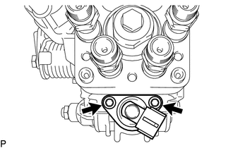
Using a 5 mm hexagon wrench, install the timing control valve sub-assembly with the 2 bolts.
- Torque:
- 8.4 N*m (86 kgf*cm, 74 in.*lbf)
22.INSTALL CAP SEAL
Install the full load set screw.
Install a new cap seal.
23.INSTALL HIGH ALTITUDE COMPENSATOR (w/ HAC)
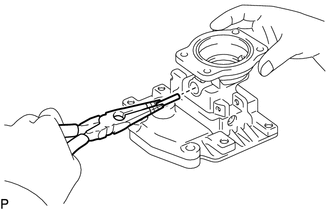
Insert the connecting pin into the governor cover.
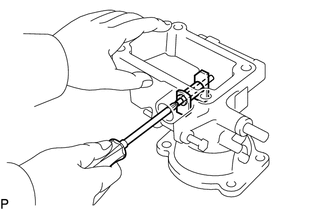
Using a small screwdriver, install the control lever with the support pin.
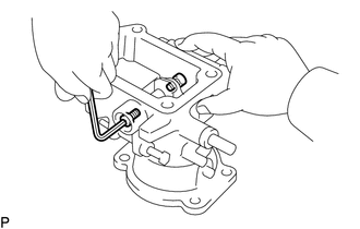
Using a 4 mm hexagon wrench, install 2 new gaskets and the 2 bolts.
- Torque:
- 6.9 N*m (70 kgf*cm, 61 in.*lbf)
22540 24.INSTALL BOOST COMPENSATOR SUB-ASSEMBLY (w/ BACS)
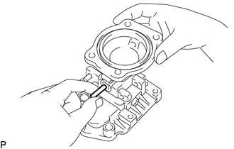
Insert the connecting pin into the governor cover.
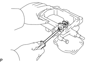
Using a small screwdriver, install the control lever with the support pin.
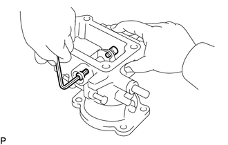
Using a 4 mm hexagon wrench, install 2 new gaskets and the 2 bolts.
- Torque:
- 6.9 N*m (70 kgf*cm, 61 in.*lbf)
22701 25.INSTALL ADJUSTING LEVER SHAFT TO GOVERNOR SHAFT (w/o BACS)
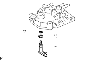
| *1 | Adjusting Lever Shaft |
| *2 | O-ring |
| *3 | Washer |
Install the following parts to the governor cover:
Plate washer
New O-ring
Adjusting lever shaft, O-ring and plate washer assembly
22701 26.INSTALL ADJUSTING LEVER SHAFT TO GOVERNOR LINK (w/ BACS)
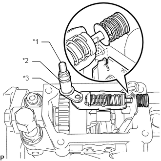
| *1 | Adjusting Lever Shaft |
| *2 | O-ring |
| *3 | Washer |
Install the following parts to the governor link:
Adjusting lever shaft
Plate washer
New O-ring
22703B 27.INSTALL GOVERNOR COVER (w/o BACS)
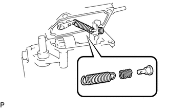
Install the speed control spring to the adjusting shaft.
Install a new gasket to the groove of the governor cover.
Install the damper spring and spring seat, and connect the speed control spring to the spring seat.
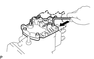
Using a 5 mm hexagon wrench, install the governor cover with the 4 bolts.
- Torque:
- 8.3 N*m (85 kgf*cm, 73 in.*lbf)
- HINT:
-
Use a bolt that is 35 mm (1.38 in.) in length.
w/ HAC:
Install the idle speed adjusting screw.
- Torque:
- 6.9 N*m (70 kgf*cm, 61 in.*lbf)
22703B 28.INSTALL GOVERNOR COVER (w/ BACS)
Install the adjusting lever shaft to the governor cover.
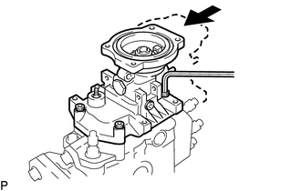
Using a 5 mm hexagon wrench, install the governor cover with the 4 bolts.
- Torque:
- 8.3 N*m (85 kgf*cm, 73 in.*lbf)
- HINT:
-
Use a bolt that is 35 mm (1.38 in.) in length.
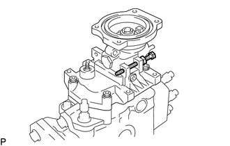
Install the idle speed adjusting screw.
- Torque:
- 6.9 N*m (70 kgf*cm, 61 in.*lbf)
22701 29.INSTALL ADJUSTING LEVER (w/o BACS)
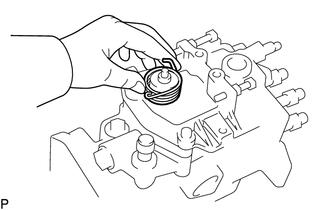
Place the return spring on the governor cover.
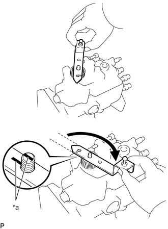
| *a | Matchmark |
Hook the return spring to the adjusting lever, and turn and place the adjusting lever on the governor shaft.
Align the lines of the adjusting lever shaft and adjusting lever.
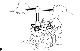
Install the adjusting lever with the spring guide and nut.
- Torque:
- 8.4 N*m (86 kgf*cm, 74 in.*lbf)
22701 30.INSTALL ADJUSTING LEVER (w/ BACS)
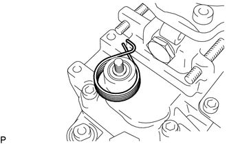
Place the return spring on the governor cover.
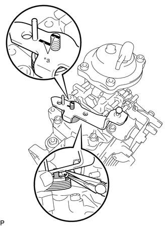
| *a | Matchmark |
Install the return spring to the adjusting lever shown in the illustration.
Align the lines of the adjusting lever shaft and adjusting lever.
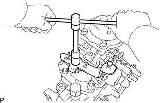
Install the adjusting lever with the spring guide and nut.
- Torque:
- 8.4 N*m (86 kgf*cm, 74 in.*lbf)
31.INSTALL THROTTLE POSITION SENSOR BRACKET (w/ BACS)
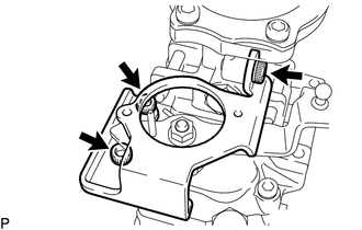
Using a 5 mm hexagon wrench, install the throttle position sensor bracket with the 3 bolts.
- Torque:
- 8.4 N*m (86 kgf*cm, 74 in.*lbf)
32.INSTALL THROTTLE POSITION SENSOR (w/ BACS)
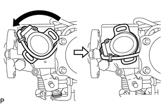
Set the throttle position sensor as shown in the illustration.
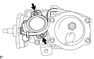
Temporarily install the throttle position sensor with the 2 screws.
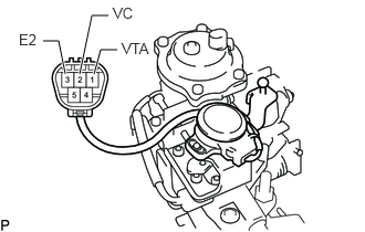
Apply 4.99 to 5.01 V across terminals 2 (VC) and 3 (E2).
Connect the tester probes of a voltmeter to terminals 1 (VTA) and 3 (E2) of the throttle position sensor.
Secure the adjusting lever fully on the maximum speed side so that its output will be 0.575 to 0.625 V.
Tighten the 2 screws holding the throttle position sensor to the bracket.
- Torque:
- 1.7 N*m (17 kgf*cm, 15 in.*lbf)
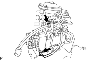
Using a 5 mm hexagon wrench, install the bolt.
- Torque:
- 8.4 N*m (86 kgf*cm, 74 in.*lbf)
Connect the timing control valve connector.
33.INSTALL PICKUP SENSOR (w/ TACHOMETER)
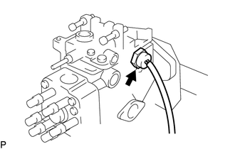
Install a new O-ring and pickup sensor.
Connect the 2 lead wires to the connector.
- Torque:
- 21 N*m (214 kgf*cm, 15 ft.*lbf)
34.ADJUST PLUNGER PRE-STROKE
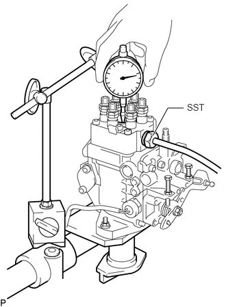
Insert SST to the fuel cut solenoid installation screw section.
- SST
-
09275-17010
Set the dial indicator so that the tip of the dial indicator push rod touches the upper surface of the plunger.
Rotate the drive shaft, set the plunger to BDC and set the scale on the dial indicator to 0 mm (0 in.).
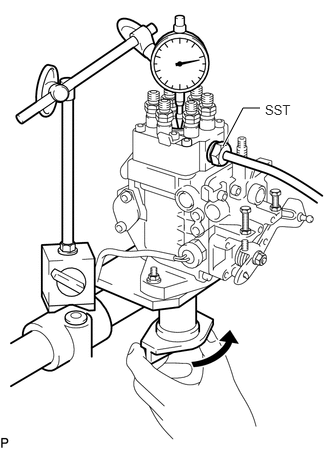
Apply a few drops of light oil (diesel fuel) to the top surface of the plunger, and when 49 kPa (0.1 kg/cm, 1.4 psi) of air is applied to SST, bubbles appear on the upper surface of the plunger.
- SST
-
09275-17010
Slowly rotate the drive shaft in the pump rotation direction (clockwise) and read the dial indicator when the bubbles on the top of the plunger disappear.
- Pre-stroke:
-
0.15 to 0.25 mm (0.00591 to 0.00984 in.)
If the pre-stroke is not as specified, replace the plunger adjusting shim under the plunger with a different sized shim.
- Adjusting Shim Thickness:
-
Specified Condition 1.90 mm (0.0748 in.) 2.35 mm (0.0925 in.) 2.80 mm (0.1102 in.) 1.95 mm (0.0768 in.) 2.40 mm (0.0945 in.) 2.85 mm (0.1122 in.) 2.00 mm (0.0787 in.) 2.45 mm (0.0965 in.) 2.90 mm (0.1142 in.) 2.05 mm (0.0807 in.) 2.50 mm (0.0984 in.) 2.94 mm (0.1157 in.) 2.10 mm (0.0827 in.) 2.55 mm (0.1004 in.) 2.99 mm (0.1177 in.) 2.15 mm (0.0846 in.) 2.60 mm (0.1024 in.) 3.04 mm (0.1197 in.) 2.20 mm (0.0866 in.) 2.65 mm (0.1043 in.) 3.09 mm (0.1217 in.) 2.25 mm (0.0886 in.) 2.70 mm (0.1063 in.) 3.14 mm (0.1236 in.) 2.30 mm (0.0906 in.) 2.75 mm (0.1083 in.) 3.19 mm (0.1256 in.)
- HINT:
-
If the shim is made thicker, the pre-stroke is decreased.
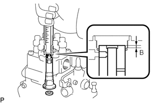
After completing the pre-stroke adjustment, check that dimension B is within the specification.
- Standard Dimension B:
-
3.15 to 3.45 mm (0.124 to 0.136 in.)2.8 to 3.2 mm (0.110 to 0.126 in.)
If dimension B is not within the specification, replace the distributor head.
22176 35.INSTALL DISTRIBUTIVE HEAD PLUG
Install a new gasket and the distributive head plug bolt.
- Torque:
- 16.7 N*m (170 kgf*cm, 12 ft.*lbf)
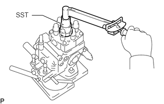
Install a new O-ring to the distributive head plug.
Using SST, install the distributive head plug.
- SST
-
09260-54012 (09262-54010)
- Torque:
- 69 N*m (704 kgf*cm, 51 ft.*lbf)
36.INSTALL HIGH ALTITUDE COMPENSATOR (w/ HAC)
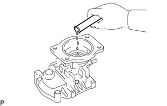
Insert 3 to 4 cc (0.18 to 0.24 cu.in.) of engine oil into the bushing hole.
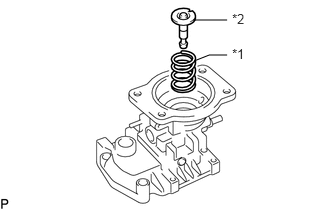
| *1 | Pneumatic Bellows Spring |
| *2 | Push Rod |
Place the following parts on the governor cover:
Pneumatic bellows spring
Push rod
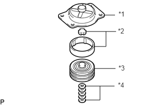
| *1 | Pneumatic Bellows Cover |
| *2 | Rubber Cap |
| *3 | Pneumatic Bellows |
| *4 | Shim |
Install the following parts to the pneumatic bellows cover:
Pneumatic bellows
2 rubber caps
Pneumatic bellows
Shims
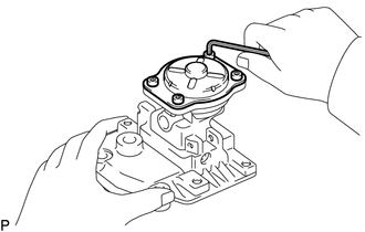
Install a new gasket and the pneumatic bellows and bellows cover assembly to the governor cover.
Using a 5 mm hexagon wrench, install the 4 bolts.
- Torque:
- 7.4 N*m (75 kgf*cm, 65 in.*lbf)
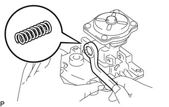
Install the lever control spring with a new gasket and the plug.
- Torque:
- 12.8 N*m (131 kgf*cm, 9 ft.*lbf)
22540 37.INSTALL BOOST COMPENSATOR SUB-ASSEMBLY (w/ BACS)
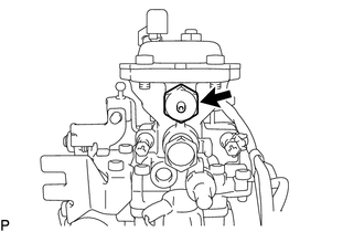
Install new gasket and a plug.
- Torque:
- 24.6 N*m (251 kgf*cm, 18 ft.*lbf)
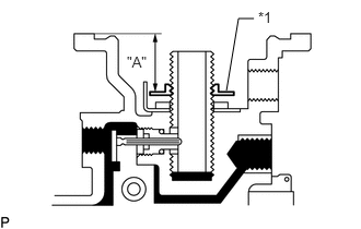
| *1 | Guide Bushing |
Install and adjust the guide bushing to the dimension A as shown in the illustration.
- Standard Dimension A:
-
18.6 to 18.7 mm (0.732 to 0.736 in.)
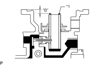
| *1 | Shim |
Adjust the boost compensator shim.
Place the shim on the guide bushing.
Using a vernier caliper, measure the dimension B as shown in the illustration.
- Standard Dimension B:
-
2.94 to 3.14 mm (0.116 to 0.124 in.)
If the dimension is not within the specification, select and install the correct shim.
Adjust the installation direction of the boost compensator diaphragm.
Install the shim and diaphragm.
- HINT:
-
Do not assemble the spring.
Place matchmarks on the diaphragm and governor cover.
Remove the diaphragm.
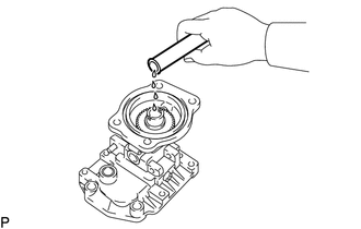
Insert 1.5 to 2.5 cc (0.09 to 0.15 cu.in.) of engine oil into the bushing hole.
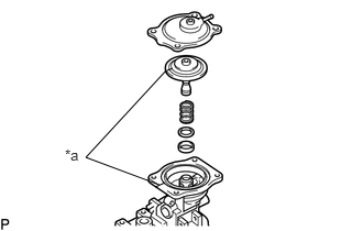
| *a | Matchmark |
Install the spring, shim and diaphragm.
Align the matchmarks on the diaphragm and governor cover.
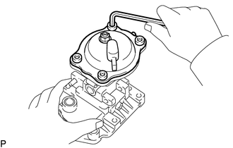
Using a 5 mm hexagon wrench, install the 4 bolts.
- Torque:
- 7.4 N*m (75 kgf*cm, 65 in.*lbf)
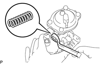
Install the lever control spring with a new gasket and the plug.
- Torque:
- 12.8 N*m (131 kgf*cm, 9 ft.*lbf)
22390A 38.INSTALL FUEL CUT SOLENOID
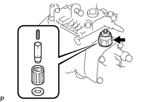
Install a new O-ring on the fuel cut solenoid.
Install the strainer, valve, spring, a new gasket and the fuel cut solenoid.
- Torque:
- 22 N*m (224 kgf*cm, 16 ft.*lbf)
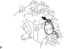
Install the lead wire to the fuel cut solenoid with the nut.
- Torque:
- 1.7 N*m (17 kgf*cm, 15 in.*lbf)
Install the dust cover to the fuel cut solenoid.
Install the lead wire connector to the bracket.
39.INSTALL THERMO WAX (w/ ACSD)
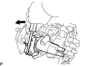
Using a screwdriver, turn the cold starting lever counterclockwise approx. 20°.
Put a metal plate (thickness of 3.5 to 7.5 mm) (0.138 to 0.295 in.) between the cold starting lever and thermo wax plunger.
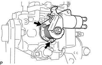
Install a new O-ring and the thermo wax with the 2 bolts.
- Torque:
- 6.9 N*m (70 kgf*cm, 61 in.*lbf)
40.INSTALL IDLE-UP LEVER (w/ ACSD)
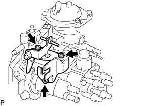
Using a 5 mm hexagon wrench, install the idle-up lever with the 3 bolts.
- Torque:
- 8.4 N*m (86 kgf*cm, 74 in.*lbf)
23770 41.INSTALL NO. 2 NOZZLE LEAKAGE PIPE ASSEMBLY
Install the 2 gaskets and No. 2 nozzle leakage pipe assembly with the union bolt.
- Torque:
- 22.1 N*m (225 kgf*cm, 16 ft.*lbf)
23811 42.INSTALL FUEL FILTER TO INJECTION PUMP FUEL PIPE
Install the 2 gaskets and fuel filter to injection pump fuel pipe with the union bolt.
- Torque:
- 24.5 N*m (250 kgf*cm, 18 ft.*lbf)
88031 43.INSTALL IDLE-UP ACTUATOR (w/ Air Conditioning System)
w/ ACSD:
Tighten the nut and install the idle-up actuator.
- Torque:
- 9.3 N*m (95 kgf*cm, 82 in.*lbf)
w/o ACSD:
Install the idle-up actuator with the 2 bolts.
- Torque:
- 7.85 N*m (80 kgf*cm, 69 in.*lbf)
44.REMOVE INJECTION PUMP FROM SST
45.PERFORM AIRTIGHTNESS TEST
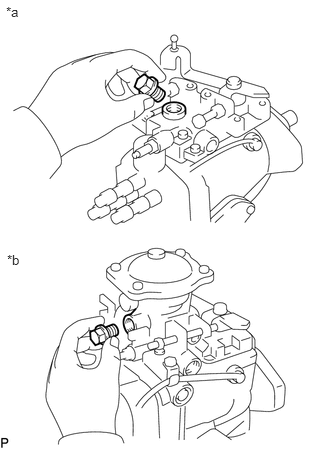
| *a | w/o HAC |
| *b | w/ HAC |
Install a bolt to the overflow port.
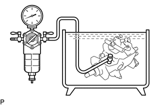
Connect an air hose to the fuel inlet pipe and place the injection pump into the diesel.
Apply 49 kPa (0.5 kgf/cm2, 7 psi) of pressure and confirm that there are no leaks.
Check that there are no leaks with 490 kPa (5.0 kgf/cm2, 71 psi) of pressure applied.
46.INSTALL SET KEY OF INJECTION PUMP DRIVE PULLEY ON DRIVE SHAFT