METER / GAUGE / DISPLAY METER / GAUGE SYSTEM TERMINALS OF ECU
CHECK COMBINATION METER ASSEMBLY
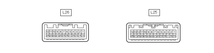
Measure the voltage, resistance and waveform according to the value(s) in the table below.
| Terminal No. | Wiring Color | Terminal Description | Condition | Specified Condition |
|---|---|---|---|---|
|
*1: w/ Front Fog Light *2: w/ Rear Fog Light *3: for 1GR-FE *4: w/o ABS *5: w/ ABS *6: for 1VD-FTV, 1HZ *7: for 1VD-FTV *8: Oil Pressure Gauge *9: for Double Tank Type *10: w/ Airbag System *11: w/o Airbag System *12: for 1VD-FTV, 1HZ (w/ Oil Pressure Gauge) *13: w/ Immobiliser System *14: for 1HZ *15: w/ Differential Lock *16: w/ Key Reminder Warning System *17: w/ Seat Belt Warning System |
||||
| L25-1 (FOG) - L25-15 (ES)*1 | R-B - BR | FRONT FOG indicator light signal | Ignition switch ON, front fog indicator light on | 11 to 14 V |
| Ignition switch ON, front fog indicator light off | Below 1 V | |||
| L25-2 (SW) - L25-15 (ES) | B-L - BR | 4WD indicator light signal | Ignition switch ON, 4WD indicator light on | Below 1 V |
| Ignition switch ON, 4WD indicator light off | 11 to 14 V | |||
| L25-3 (+) - L25-15 (ES)*2 | R-L - BR | REAR FOG indicator light signal | Ignition switch ON, rear fog indicator light on | 11 to 14 V |
| Ignition switch ON, rear fog indicator light off | Below 1 V | |||
| L25-5 (ILL+) - L25-15 (ES) | G - BR | Illumination light signal | Light control switch off | Below 1 V |
| Light control switch TAIL or HEAD | 11 to 14 V | |||
| L25-6 (DOOR) - L25-15 (ES) | B-W - BR | DOOR warning light signal | A door is open | Below 1 V |
| All door are closed | 11 to 14 V | |||
| L25-7 (SW) - L25-15 (ES) | B - BR | DOOR warning light signal | Doors open (Disregarding driver side door) | Below 1 V |
| Doors closed (Disregarding driver side door) | 11 to 14 V | |||
| L25-8 (+S) - L25-15 (ES) | G - BR | Speed signal (output) | Driving at approximately 20 km/h (12 mph) | Pulse generation (See waveform 1) |
| L25-9 (SI) - L25-15 (ES) | G-R - BR | Speed signal (input) | Driving at approximately 20 km/h (12 mph) | Pulse generation (See waveform 1) |
| L25-10 (S) - L25-15 (ES) | B - BR | Tachometer signal | Engine idling | Pulse generation |
| L25-11 (S) - L25-15 (ES)*3 | Y-G - BR | Engine coolant temperature sensor signal | Engine running, engine coolant temperature 80°C (176°F) | Pulse generation (See waveform 2) |
| L25-13 (IG+) - L25-15 (ES)*4 | L - BR | Speed sensor power supply | Ignition switch ON | 11 to 14 V |
| Ignition switch off | Below 1 V | |||
| L25-15 (ES) - Body ground | BR - Body ground | Ground | Always | Below 1 V |
| L25-16 (LP) - Body ground*4 | V - Body ground | Ground | Always | Below 1 V |
| L25-16 (LP) - L25-15 (ES)*5 | V - BR | ABS warning light signal | Ignition switch ON, ABS warning light on | 11 to 14 V |
| Ignition switch ON, ABS warning light off | Below 1 V | |||
| L25-17 (FRSW) - L25-15 (ES)*15 | R-Y - BR | Front differential lock indicator light signal | Ignition switch ON, front differential lock indicator light on | Below 1 V |
| Ignition switch ON, front differential lock indicator light off | 11 to 14 V | |||
| L25-18 (RRSW) - L25-15 (ES)*15 | R-L - BR | Rear differential lock indicator light signal | Ignition switch ON, rear differential lock indicator light on | Below 1 V |
| Ignition switch ON, rear differential lock indicator light off | 11 to 14 V | |||
| L25-19 (SW) - L25-15 (ES)*16 | B-R - BR | Unlock warning switch assembly signal | Key in ignition key cylinder | Below 1 V |
| No key in ignition key cylinder | 11 to 14 V | |||
| L25-20 (PKBI) - L25-15 (ES) | R-W - BR | Parking brake switch assembly signal | Parking brake switch assembly on | Below 1 V |
| Parking brake switch assembly off | 11 to 14 V | |||
| L25-21 (SW) - L25-15 (ES)*17 | P - BR | Seat belt warning light signal | Ignition switch ON, driver side seat buckle switch is fastened | Below 1 V |
| Ignition switch ON, driver side seat buckle switch is unfastened | 11 to 14 V ←→ Below 1 V | |||
| L25-22 (S) - L25-15 (ES)*6 | G-B - BR | Fuel sediment switch signal | Ignition switch ON, FUEL SEDIMENT warning light on | Below 1 V |
| Ignition switch ON, FUEL SEDIMENT warning light off | 11 to 14 V | |||
| L25-23 (FFTR) - L25-15 (ES)*7 | W - BR | Fuel filter vacuum sensor signal | Ignition switch ON, FUEL FILTER warning light on | 11 to 14 V |
| Ignition switch ON, FUEL FILTER warning light off | Below 1 V | |||
| L25-24 (OIL) - L25-15 (ES)*7 | B-R - BR | Engine oil level sensor signal | Ignition switch ON, OIL LEVEL warning light on | 11 to 14 V |
| Ignition switch ON, OIL LEVEL warning light off | Below 1 V | |||
| L25-26 (B) - Body ground | R - Body ground | Battery | Always | 11 to 14 V |
| L25-28 (B) - Body ground | B-Y - Body ground | Battery | Always | 11 to 14 V |
| L26-1 (CHG-) - L25-15 (ES) | Y - BR | CHARGE warning light signal | Ignition switch ON, CHARGE warning light on | Below 1 V |
| Ignition switch ON, CHARGE warning light off | 11 to 14 V | |||
| L26-2 (+) - L25-15 (ES) | L-W - BR | HI BEAM indicator light signal | Ignition switch ON, HI BEAM indicator light off | Below 1 V |
| Ignition switch ON, HI BEAM indicator light on | 11 to 14 V | |||
| L26-3 (SW) - L25-15 (ES) | R-W - BR | BRAKE warning light signal | BRAKE warning light on | Below 1 V |
| BRAKE warning light off | 11 to 14 V | |||
| L26-4 (OIL1) - L25-15 (ES)*8 | B-R - BR | OIL PRESSURE warning light signal | Ignition switch ON, OIL PRESSURE warning light on | Below 1 V |
| Ignition switch ON, OIL PRESSURE warning light off | 11 to 14 V | |||
| L26-5 (B) - L25-15 (ES) | G-B - BR | Turn signal indicator LH signal | Ignition switch ON, turn signal indicator LH light off | Below 1 V |
| Ignition switch ON, turn signal indicator LH light on | 11 to 14 V ←→ Below 1 V | |||
| L26-6 (B) - L25-15 (ES) | G-Y - BR | Turn signal indicator RH signal | Ignition switch ON, turn signal indicator RH light off | Below 1 V |
| Ignition switch ON, turn signal indicator RH light on | 11 to 14 V ←→ Below 1 V | |||
| L26-10 (L) - L26-14 (FE)*9 | Y-R - BR | Fuel receiver gauge assembly (sub) signal | Ignition switch ON, fuel F (full tank) | 12 to 18 Ω |
| Ignition switch ON, E (empty) | 405 to 415 Ω | |||
| L26-11 (IND) - L25-15 (ES)*9 | B-R - BR | SUB indicator light signal | Ignition switch ON, SUB indicator light on | Below 1 V |
| Ignition switch ON, SUB indicator light off | 11 to 14 V | |||
| L26-12 (L) - L26-13 (FE) | Y-R - BR | Fuel receiver gauge assembly signal | Ignition switch ON, fuel F (full tank) | 12 to 18 Ω |
| Ignition switch ON, E (empty) | 405 to 415 Ω | |||
| L26-16 (IG+) - L25-15 (ES)*3 | B-R - BR | Oil pressure sender gauge assembly power source | Ignition switch ON | 4.75 to 5.25 V |
| Ignition switch off | Below 1 V | |||
| L26-17 (S) - L25-15 (ES)*3 | L - BR | Oil pressure sender gauge assembly signal | Ignition switch ON | 0.14 to 0.9 V |
| L26-18 (FR) - L25-15 (ES)*6 | Y-G - BR | Engine coolant temperature sensor signal | Engine is warmed up: Idling, engine coolant temperature at 60 to 120°C (140 to 248°F)*7 | 0.2 to 1.2 V |
| Engine is warmed up: Idling, engine coolant temperature at 80°C (176°F)*14 | 0.2 to 1.0 V | |||
| L26-19 (A/B) - L25-15 (ES)*10 | R - BR | SRS warning light signal | Ignition switch ON, SRS warning light off | 11 to 14 V |
| Ignition switch ON, SRS warning light on | Below 1 V | |||
| L26-19 (A/B) - L25-15 (ES)*11 | R - BR | IG power supply | Ignition switch off | Below 1 V |
| Ignition switch ON | 11 to 14 V | |||
| L26-20 (S) - L25-15 (ES)*12 | B-R - BR | Oil pressure sender gauge signal | Ignition switch off | Below 1 V |
| Ignition switch ON | 4.3 to 15.2 V | |||
| L26-21 (CHK) - L25-15 (ES) | R-W - BR | MIL signal | Ignition switch ON, MIL on | Below 1 V |
| Ignition switch ON, MIL off | 11 to 14 V | |||
| L26-22 (GLW-) - L25-15 (ES)*6 | R-W - BR | GLOW warning light signal | Ignition switch ON, GLOW indicator light on | Below 1 V |
| Ignition switch ON, GLOW indicator light off | 11 to 14 V | |||
| L26-23 (LP) - L25-15 (ES)*13 | G-R - BR | SECURITY warning light signal | Immobiliser unset | Below 1 V |
| Immobiliser set | 11 to 14 V ←→ Below 1 V | |||
| L26-24 (E) - L25-15 (ES)*3 | W-B - BR | Oil pressure sender gauge assembly ground | Always | Below 1 V |
| Terminal No. | Wiring Color | Terminal Description | Condition | Specified Condition |
|---|---|---|---|---|
|
*: for Double Tank Type |
||||
| L25-2 (SW) - L25-15 (ES) | B-L - BR | 4WD indicator light signal | Ignition switch ON, 4WD indicator light on | Below 1 V |
| Ignition switch ON, 4WD indicator light off | 20 to 28 V | |||
| L25-5 (ILL+) - L25-15 (ES) | G - BR | Illumination light signal | Light control switch off | Below 1 V |
| Light control switch TAIL or HEAD | 20 to 28 V | |||
| L25-6 (DOOR) - L25-15 (ES) | B-W - BR | DOOR warning light signal | A door is open | Below 1 V |
| All door are closed | 20 to 28 V | |||
| L25-7 (SW) - L25-15 (ES) | B - BR | DOOR warning light signal | Doors open (Disregarding driver side door) | Below 1 V |
| Doors closed (Disregarding driver side door) | 20 to 28 V | |||
| L25-8 (+S) - L25-15 (ES) | G - BR | Speed signal (output) | Driving at approximately 20 km/h (12 mph) | Pulse generation (See waveform 1) |
| L25-9 (SI) - L25-15 (ES) | G-R - BR | Speed signal (input) | Driving at approximately 20 km/h (12 mph) | Pulse generation (See waveform 1) |
| L25-13 (IG+) - L25-15 (ES) | L - BR | Speed sensor power supply | Ignition switch ON | 11 to 14 V |
| Ignition switch off | Below 1 V | |||
| L25-15 (ES) - Body ground | BR - Body ground | Ground | Always | Below 1 V |
| L25-17 (FRSW) - L25-15 (ES) | R-Y - BR | Front differential lock indicator light signal | Ignition switch ON, front differential lock indicator light on | Below 1 V |
| Ignition switch ON, front differential lock indicator light off | 20 to 28 V | |||
| L25-18 (RRSW) - L25-15 (ES) | R-L - BR | Rear differential lock indicator light signal | Ignition switch ON, rear differential lock indicator light on | Below 1 V |
| Ignition switch ON, rear differential lock indicator light off | 20 to 28 V | |||
| L25-19 (SW) - L25-15 (ES) | B-R - BR | Unlock warning switch assembly signal | Key in ignition key cylinder | Below 1 V |
| No key in ignition key cylinder | 20 to 28 V | |||
| L25-20 (PKBI) - L25-15 (ES) | R-W - BR | Parking brake switch assembly signal | Parking brake switch assembly on | Below 1 V |
| Parking brake switch assembly off | 20 to 28 V | |||
| L25-22 (S) - L25-15 (ES) | G-B - BR | Fuel sediment switch signal | Ignition switch ON, FUEL SEDIMENT warning light on | Below 1 V |
| Ignition switch ON, FUEL SEDIMENT warning light off | 20 to 28 V | |||
| L25-26 (B) - Body ground | R - Body ground | Battery | Always | 20 to 28 V |
| L25-28 (B) - Body ground | B-Y - Body ground | Battery | Always | 20 to 28 V |
| L26-1 (CHG-) - L25-15 (ES) | Y - BR | CHARGE warning light signal | Ignition switch ON, CHARGE warning light on | Below 1 V |
| Ignition switch ON, CHARGE warning light off | 20 to 28 V | |||
| L26-2 (+) - L25-15 (ES) | L-W - BR | HI BEAM indicator light signal | Ignition switch ON, HI BEAM indicator light off | Below 1 V |
| Ignition switch ON, HI BEAM indicator light on | 20 to 28 V | |||
| L26-3 (SW) - L25-15 (ES) | R-W - BR | BRAKE warning light signal | BRAKE warning light on | Below 1 V |
| BRAKE warning light off | 20 to 28 V | |||
| L26-4 (OIL1) - L25-15 (ES) | B-R - BR | OIL PRESSURE warning light signal | Ignition switch ON, OIL PRESSURE warning light on | Below 1 V |
| Ignition switch ON, OIL PRESSURE warning light off | 20 to 28 V | |||
| L26-5 (B) - L25-15 (ES) | G-B - BR | Turn signal indicator LH signal | Ignition switch ON, turn signal indicator LH light off | Below 1 V |
| Ignition switch ON, turn signal indicator LH light on | 20 to 28 V ←→ Below 1 V | |||
| L26-6 (B) - L25-15 (ES) | G-Y - BR | Turn signal indicator RH signal | Ignition switch ON, turn signal indicator RH light off | Below 1 V |
| Ignition switch ON, turn signal indicator RH light on | 20 to 28 V ←→ Below 1 V | |||
| L26-11 (IND) - L25-15 (ES)* | B-R - BR | SUB indicator light signal | Ignition switch ON, SUB indicator light on | Below 1 V |
| Ignition switch ON, SUB indicator light off | 20 to 28 V | |||
| L26-12 (L) - L26-13 (FE) | Y-R - BR | Fuel receiver gauge assembly signal | Ignition switch ON, fuel F (full tank) | 12 to 18 Ω |
| Ignition switch ON, E (empty) | 405 to 415 Ω | |||
| L26-18 (FR) - L25-15 (ES) | Y-G - BR | Engine coolant temperature sensor signal | Engine is warmed up: Idling, engine coolant temperature at 80°C (176°F) | 0.2 to 1.0 V |
| L26-19 (A/B) - L25-15 (ES) | R - BR | IG power supply | Ignition switch off | Below 1 V |
| Ignition switch ON | 20 to 28 V | |||
| L26-22 (GLW-) - L25-15 (ES) | R-W - BR | GLOW warning light signal | Ignition switch ON, GLOW indicator light on | Below 1 V |
| Ignition switch ON, GLOW indicator light off | 20 to 28 V | |||
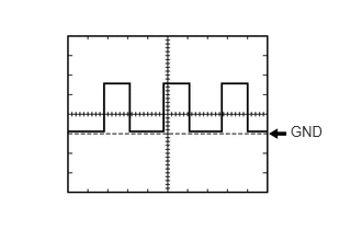
Using an oscilloscope, check waveform 1.
| Item | Condition |
|---|---|
| Tester Connection |
·
L25-8 (+S) - L25-15 (ES)
·
L25-9 (SI) - L25-15 (ES) |
| Tool Setting | 5 V/DIV., 20 msec./DIV. |
| Condition | Driving at approximately 20 km/h (12 mph) |
- HINT:
-
As the vehicle speed increases, the wavelength shortens.
Using an oscilloscope, check waveform 2.
| Item | Condition |
|---|---|
| Tester Connection | L25-11 (S) - L25-15 (ES) |
| Tool Setting | 5 V/DIV., 10 msec./DIV. |
| Condition | Engine running, engine coolant temperature 80°C (176°F) |
- HINT:
-
As the coolant temperature rises, the period "A" shown in the illumination becomes longer.