RM25T0E _56 Audio / Visual / Telematics _029922 AUDIO / VIDEO _0137647 AUDIO AND VISUAL SYSTEM U
AUDIO / VIDEO AUDIO AND VISUAL SYSTEM TERMINALS OF ECU
RADIO RECEIVER ASSEMBLY (w/ CD Player)
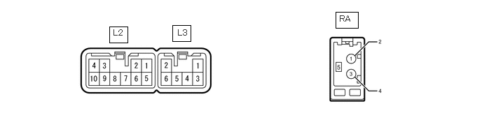
1.625,0.396 1.896,0.635 0.271,0.24 2.563,0.375 2.833,0.615 0.271,0.24 4.99,0.177 5.323,0.417 0.333,0.24 1.688,0.417 2.01,0.625 0.323,0.208 10 false L2 2.646,0.417 2.969,0.625 0.323,0.208 10 false L3 5.052,0.208 5.375,0.417 0.323,0.208 10 false RA
| Terminal No. (Symbol) | Wiring Color | Terminal Description | Condition | Specified Condition |
|---|---|---|---|---|
|
*1: for 4 Speakers *2: for Electric Type Antenna #: There is no wire color information. |
||||
| L2-1 (FR+) - L2-7 (E) | LG - BR | Sound signal (Front right) | Audio system playing | A waveform synchronized with video signals is output |
| L2-2 (FL+) - L2-7 (E) | P - BR | Sound signal (Front left) | Audio system playing | A waveform synchronized with video signals is output |
| L2-3 (ACC) - L2-7 (E) | GR - BR | Accessory (On) | Ignition switch off | Below 1 V |
| Ignition switch ACC | 11 to 14 V | |||
| L2-4 (B) - L2-7 (E) | R - BR | Battery | Always | 11 to 14 V |
| L2-5 (FR-) - L2-7 (E) | L - BR | Sound signal (Front right) | Audio system playing | A waveform synchronized with video signals is output |
| L2-6 (FL-) - L2-7 (E) | V - BR | Sound signal (Front left) | Audio system playing | A waveform synchronized with video signals is output |
| L2-7 (E) - Body ground | BR - Body ground | Ground | Always | Below 1 Ω |
| L2-10 (ILL+) - L2-7 (E) | G - BR | Illumination signal | Headlight dimmer switch assembly off | Below 1 V |
| Headlight dimmer switch assembly tail or head position | 11 to 14 V | |||
| L3-1 (RR+) - L2-7 (E)*1 | R - BR | Sound signal (Rear right) | Audio system playing | A waveform synchronized with video signals is output |
| L3-2 (RL+) - L2-7 (E)*1 | B - BR | Sound signal (Rear left) | Audio system playing | A waveform synchronized with video signals is output |
| L3-3 (RR-) - L2-7 (E)*1 | W - BR | Sound signal (Rear right) | Audio system playing | A waveform synchronized with video signals is output |
| L3-6 (RL-) - L2-7 (E)*1 | Y - BR | Sound signal (Rear left) | Audio system playing | A waveform synchronized with video signals is output |
| RA-3 (MAIN) - Body ground | # - Body ground | - | - | - |
| RA-5 (ANT+) - L2-7 (E)*2 | # - BR | Power source of antenna | Ignition switch ACC, radio switch on and FM or AM selected | 11 to 14 V |
RADIO RECEIVER ASSEMBLY (w/o CD Player)

3.344,0.333 3.833,0.563 0.49,0.229 3.521,0.354 3.833,0.552 0.313,0.198 10 false L2
| Terminal No. (Symbol) | Wiring Color | Terminal Description | Condition | Specified Condition |
|---|---|---|---|---|
|
*1: for RHD *2: for LHD *3: for Electric Type Antenna |
||||
| L2-1 (FR+) - L2-7 (E)*1 | LG - BR | Sound signal (Front right) | Audio system playing | A waveform synchronized with video signals is output |
| L2-2 (FL+) - L2-7 (E)*2 | P - BR | Sound signal (Front left) | Audio system playing | A waveform synchronized with video signals is output |
| L2-3 (ACC) - L2-7 (E) | GR - BR | Accessory (On) | Ignition switch off | Below 1 V |
| Ignition switch ACC | 11 to 14 V | |||
| L2-4 (B) - L2-7 (E) | R - BR | Battery | Always | 11 to 14 V |
| L2-5 (FR-) - L2-7 (E)*1 | L - BR | Sound signal (Front right) | Audio system playing | A waveform synchronized with video signals is output |
| L2-6 (FL-) - L2-7 (E)*2 | V - BR | Sound signal (Front left) | Audio system playing | A waveform synchronized with video signals is output |
| L2-7 (E) - Body ground | BR - Body ground | Ground | Always | Below 1 Ω |
| L2-8 (ANT) - L2-7 (E)*3 | L-Y - BR | Power source of antenna | Ignition switch ACC, radio switch on and FM or AM selected | 11 to 14 V |