H150F MANUAL TRANSMISSION / TRANSAXLE OUTPUT SHAFT REASSEMBLY
PROCEDURE

 33395 1.INSTALL NO. 3 TRANSMISSION HUB SLEEVE
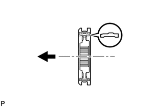

|
Front Side |
Apply gear oil to the joint spline of the No. 3 transmission clutch hub and No. 3 transmission hub sleeve.
Install the No. 3 transmission hub sleeve to the No. 3 transmission clutch hub.
- NOTICE:
-
Do not mistake the installation direction of the No. 3 transmission hub sleeve and No. 3 transmission clutch hub.
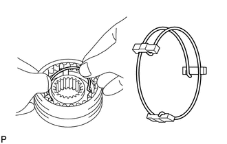
Install the 3 shifting keys to the No. 3 transmission clutch hub and secure with the 2 springs.
- NOTICE:
-
·
Install the shifting keys in the correct direction.
·Position the springs so that their end gaps are not facing in the same direction.
33369 2.INSTALL NO. 3 SYNCHRONIZER RING
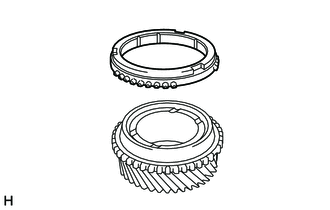
Coat the No. 3 synchronizer ring with gear oil, and set it onto the 5th gear.
33428B 3.INSTALL COUNTER 5TH GEAR BEARING
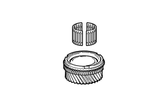
Coat the counter 5th gear bearing with gear oil, and install it to the 5th gear.
33336 4.INSTALL 5TH GEAR
Apply gear oil to the thrust surface and inner diameter surface of the 5th gear and install it to the output shaft.
|
|
Front Side |
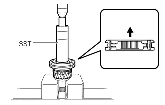
Using SST and a press, install the No. 3 transmission clutch hub to the output shaft.
- SST
-
09316-60011 (09316-00011)
- NOTICE:
-
·
Install in the correct direction.
·Align the key groove of the No. 3 synchronizer ring with the shifting key when installing.
Check that the 5th gear lightly rotates and the No. 3 synchronizer ring is not stuck.
5.INSPECT 5TH GEAR THRUST CLEARANCE
6.INSPECT 5TH GEAR RADIAL CLEARANCE
33393A 7.INSTALL NO. 3 TRANSMISSION CLUTCH HUB SHAFT SNAP RING
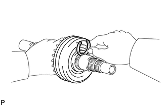
Select a new snap ring that will allow minimum clearance.
| Mark | Thickness |
|---|---|
| A | 2.40 to 2.45 mm (0.0945 to 0.0964 in.) |
| B | 2.45 to 2.50 mm (0.0965 to 0.0984 in.) |
| C | 2.50 to 2.55 mm (0.0985 to 0.1003 in.) |
| D | 2.55 to 2.60 mm (0.1004 to 0.1023 in.) |
| E | 2.60 to 2.65 mm (0.1024 to 0.1043 in.) |
| F | 2.65 to 2.70 mm (0.1044 to 0.1062 in.) |
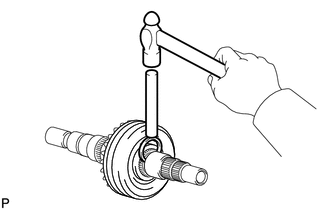
Using a brass bar and hammer, install the No. 3 transmission clutch hub shaft snap ring to the output shaft.
33333A 8.INSTALL 3RD GEAR NEEDLE ROLLER BEARING
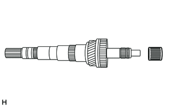
Coat the 3rd gear needle roller bearing with gear oil, and install it to the 3rd gear.
33039 9.INSTALL NO. 3 SYNCHRONIZER RING SET
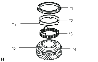
| *1 | Outer Ring |
| *2 | Middle Ring |
| *3 | Inner Ring |
| *4 | 3rd Gear |
| *a | Protrusion |
| *b | Cutout |
Apply gear oil to the No. 3 synchronizer ring set and tapered cone surface of the 3rd gear, and install the 3rd gear to the No. 3 synchronizer ring set.
- NOTICE:
-
Align the claw of the middle ring and the cutout of the 3rd gear.
36235B 10.INSTALL NO. 2 TRANSMISSION HUB SLEEVE
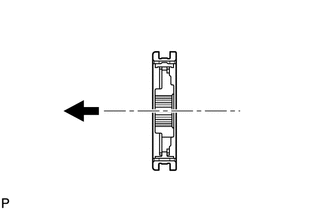
|
|
Front Side |
Apply gear oil to the joint spline of the No. 2 transmission clutch hub and No. 2 transmission hub sleeve.
Install the No. 2 transmission hub sleeve to the No. 2 transmission clutch hub.
- NOTICE:
-
Do not mistake the installation direction of the No. 2 transmission hub sleeve and No. 2 transmission clutch hub.
Install the 3 shifting keys to the No. 2 transmission clutch hub and secure with the 2 springs.
- NOTICE:
-
·
Install the shifting keys in the correct direction.
·Position the springs so that their end gaps are not facing in the same direction.
33333 11.INSTALL 3RD GEAR
Apply gear oil to the thrust surface and inner diameter surface of the 3rd gear and install it to the output shaft.
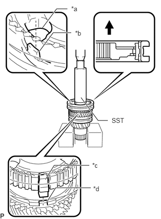
| *a | Hole of the No. 2 Transmission Clutch Hub |
| *b | Protrusion of the No. 3 Synchronizer Ring Set (Inner Ring) |
| *c | Shifting Key of the No. 2 Transmission Clutch Hub |
| *d | Groove of the No. 3 Synchronizer Ring Set (Outer Ring) |
Install the No. 2 transmission clutch hub to the output shaft.
- NOTICE:
-
·
Align the protrusion of the No. 3 synchronizer ring set (inner ring) with the hole of the No. 2 transmission clutch hub as shown in the illustration.
·Align the groove of the No. 3 synchronizer ring set (outer ring) with the shifting key of the No. 2 transmission clutch hub as shown in the illustration.
·Install in the correct direction.
Using SST and a press, install the No. 2 transmission clutch hub to the output shaft.
- SST
-
09316-60011 (09316-00011)
Check that the 3rd gear lightly rotates and the No. 3 synchronizer ring set is not stuck.
12.INSPECT 3RD GEAR THRUST CLEARANCE
13.INSPECT 3RD DRIVEN GEAR RADIAL CLEARANCE
33362A 14.INSTALL NO. 2 CLUTCH HUB SETTING SHAFT SNAP RING
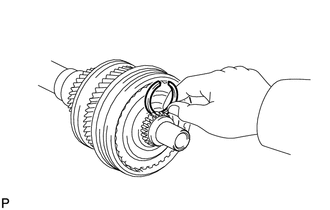
Select a new snap ring that will allow minimum clearance.
| Mark | Thickness |
|---|---|
| 4 | 1.90 to 1.95 mm (0.0749 to 0.0767 in.) |
| 5 | 1.95 to 2.00 mm (0.0768 to 0.0787 in.) |
| 6 | 2.00 to 2.05 mm (0.0788 to 0.0807 in.) |
| 7 | 2.05 to 2.10 mm (0.0808 to 0.0826 in.) |
| 8 | 2.10 to 2.15 mm (0.0827 to 0.0846 in.) |
| 9 | 2.15 to 2.20 mm (0.0847 to 0.0866 in.) |
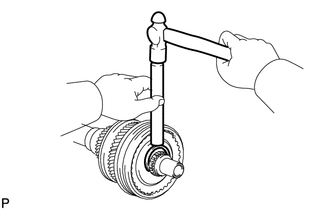
Using a brass bar and hammer, install the No. 2 transmission clutch hub shaft snap ring to the output shaft.
33332B 15.INSTALL 2ND GEAR NEEDLE ROLLER BEARING
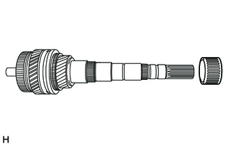
Coat the 2nd gear needle roller bearing with gear oil, and install it to the 2nd gear.
33038E 16.INSTALL NO. 2 SYNCHRONIZER RING SET
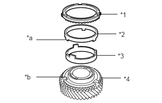
| *1 | Outer Ring |
| *2 | Middle Ring |
| *3 | Inner Ring |
| *4 | 2nd Gear |
| *a | Prutrusion |
| *b | Cutout |
Apply gear oil to the No. 2 synchronizer ring set and tapered cone surface of the 2nd gear, and install the 2nd gear to the No. 2 synchronizer ring set.
- NOTICE:
-
Align the claw of the middle ring and the cutout of the 2nd gear.
33363 17.INSTALL NO. 1 TRANSMISSION HUB SLEEVE
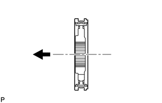
|
|
Front Side |
Apply gear oil to the joint spline of the No. 1 transmission clutch hub and No. 1 transmission hub sleeve.
Install the No. 1 transmission hub sleeve to the No. 1 transmission clutch hub.
- NOTICE:
-
Do not mistake the installation direction of the No. 1 transmission hub sleeve, No. 1 transmission clutch hub, and shifting keys.
Install the 3 shifting keys to the No. 1 transmission clutch hub and secure with the 2 springs.
- NOTICE:
-
·
Install the shifting keys in the correct direction.
·Position the springs so that their end gaps are not facing in the same direction.
33332 18.INSTALL 2ND GEAR
Apply gear oil to the thrust surface and inner diameter surface of the 2nd gear and install it to the output shaft.
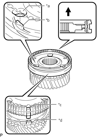
| *a | Hole of the No. 1 Transmission Clutch Hub |
| *b | Protrusion of the No. 2 Synchronizer Ring Set (Inner Ring) |
| *c | Shifting Key of the No. 1 Transmission Hub Sleeve |
| *d | Groove of the No. 2 Synchronizer Ring Set (Outer Ring) |
Install the No. 1 transmission hub sleeve with No. 1 transmission clutch hub to the 2nd gear.
- NOTICE:
-
·
Align the protrusion of the No. 2 synchronizer ring set (inner ring) with the hole of the No. 1 transmission clutch hub as shown in the illustration.
·Align the groove of the No. 2 synchronizer ring set (outer ring) with the shifting key of the No. 1 transmission clutch hub as shown in the illustration.
·Install in the correct direction.
Using SST, set the 2nd gear.
- SST
-
09316-20011
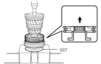
|
|
Front Side |
Using a SST and press, install the output shaft to the 2nd gear.
- NOTICE:
-
Do not drop the 2nd gear needle roller bearing.
Check that the 2nd gear lightly rotates and the No. 2 synchronizer ring set is not stuck.
19.INSPECT 2ND GEAR THRUST CLEARANCE
20.INSPECT 2ND GEAR RADIAL CLEARANCE
33361B 21.INSTALL NO. 1 CLUTCH HUB SHAFT SNAP RING
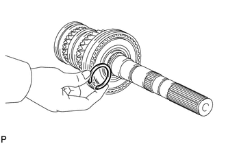
Select a new snap ring that will allow minimum clearance.
| Mark | Thickness |
|---|---|
| A | 2.90 to 2.95 mm (0.1142 to 0.1161 in.) |
| B | 2.95 to 3.00 mm (0.1162 to 0.1181 in.) |
| C | 3.00 to 3.05 mm (0.1182 to 0.1200 in.) |
| D | 3.05 to 3.10 mm (0.1201 to 0.1220 in.) |
| E | 3.10 to 3.15 mm (0.1221 to 0.1240 in.) |
| F | 3.15 to 3.20 mm (0.1241 to 0.1259 in.) |
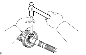
Using a brass bar and hammer, install the No. 1 transmission clutch hub shaft snap ring to the output shaft.
33335C 22.INSTALL 1ST GEAR NEEDLE ROLLER BEARING
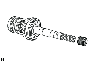
Coat the 1st gear needle roller bearing with gear oil, and install it to the 1st gear.
33367 23.INSTALL NO. 1 SYNCHRONIZER RING
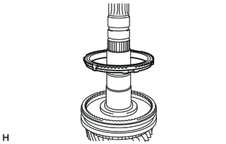
Apply gear oil to the No. 1 synchronizer ring and tapered cone surface of the 1st gear, and install the 1st gear to the No. 1 synchronizer ring.
33335 24.INSTALL 1ST GEAR
Apply gear oil to the thrust surface and inner diameter surface of the 1st gear and install it to the output shaft.
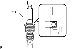
Using SST and a press, install the rear output shaft bearing to the output shaft.
- SST
-
09316-60011 (09316-00011)
09523-36010
- NOTICE:
-
·
Position the groove of the rear output shaft bearing snap ring to the rear side when installing.
·Align the key groove of the No. 1 synchronizer ring set with the shifting key when installing.
25.INSPECT 1ST GEAR THRUST CLEARANCE
26.INSPECT 1ST GEAR RADIAL CLEARANCE
33321B 27.INSTALL OUTPUT SHAFT BEARING SHAFT SNAP RING
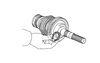
Select a new snap ring that will allow minimum clearance.
| Mark | Thickness |
|---|---|
| A | 2.40 to 2.45 mm (0.0945 to 0.0964 in.) |
| B | 2.45 to 2.50 mm (0.0965 to 0.0984 in.).) |
| C | 2.50 to 2.55 mm (0.0985 to 0.1003 in.) |
| D | 2.55 to 2.60 mm (0.1004 to 0.1023 in.) |
| E | 2.60 to 2.65 mm (0.1024 to 0.1043 in.) |
| F | 2.65 to 2.70 mm (0.1044 to 0.10629 in.) |
| G | 2.70 to 2.75 mm (0.1063 to 0.1082 in.) |
| H | 2.75 to 2.80 mm (0.1083 to 0.1102 in.) |
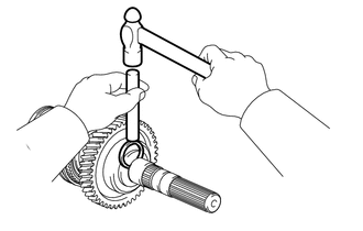
Using a brass bar and hammer, install the No. 1 transmission clutch hub shaft snap ring to the output shaft.